|
Effects pedals are far more elaborate and different than a regular guitar circuit - usually. That said, almost anything can be made into a pedal from internal guitar components such as volume and tone controls or a Varitone circuit, all the way to super elaborate DSP based stuff like pitch shifting and Digital synthesizer pedal effects.
This page is sort of an introduction to the components used in said pedals and what they are used for. Be prepared to have your mind blown. There's a lot of basic stuff in here, but I have tried to explain advanced stuff as well as I can (if I even understand it all that well).
Types of Pedals (And what likely is involved)
Here we will talk a little more first - from a player angle, before we discuss development, so you really understand what is involved and understand WHAT these pedals do electronically. We will be following the typical order by which they should be employed in the average guitar effects rig for further clarity of their role.
| NAME & PICTURE
| TYPES
| DESCRIPTION
|
DYNAMICS
| Noise Gate
Compressor
Volume
| Dynamics pedals affect the levels of a given guitar signal going into or coming out of an effects chain. These include the humble noise gate, which is a staple of modern high gain guitarists to preven that "windy noise" and "60-cycle hum" from their guitars through cranked up high gain amplifiers when not being played. Usually thsoe are based on a variablly ajustable FET transistor that sets the "Threshold" of the cut. Compressors are used to "compress" a signal, or basically, even out the lows and the highs so everything sounds like it's the same, consistant volume. You don't really hear compressor pedals so much, they are supposed to be transparent, but they are used quite a bit by guitarists who play clean, or who are trying to even out their distortion sound. Volume pedals are pretty much just a guitar volume pot on a footpedal. These were likely adopted from pedal steel guitars and found to be useful with regular spanish style electrics for similar purposes.
|
GAIN
| Fuzz
Overdrive
Distortion
Some Synths
| Gain pedals work either by clipping the signal (fuzz), overdriving the front end (preamp) of an amplifier (overdrive), or by distorting a signal before sending it to an amplifier (distortion). These are probably the most common pedals to create, and some of them are really simple by design. Fuzz Pedals typically are less as *tight* and defined by sound, and used to be marketed for making "brass instrument effects" with a guitar. Typically they work with one or a handful of transistors. Distortion pedals m ore often than not use op-amp ICs, and overdrives usually just boost the signal. Treble Boosters also belong to this particular subset as they share some similiarities with a fuzz circuit. In order of gain you have: treble booster, overdrive, distortion, fuzz. Some Fuzzes can also be octave/tone-benders/psudeo-synths because their level of gain creates a "square wave" distortion - the basis of most synthesizer type sounds.
|
FILTERS
| Wah Wah
Equilizers
Sonic Maximizers
| Filters basically take the signal sent in, and alter it in some way by filtering out certain frequencies. The most common of these being the Wah Wah pedal - which is basically a midrange filter with a cut/boost in the mid frequencies to give the guitar that sort of Peanuts Mrs. Othmar talking sound. E.Q.s are filters as well, as passive E.Q. allow you to cut signals by their frequency band, while active EQ's allow you to also BOOST those frequency bands as well. Sonic Maximizers improve clarity of the signal or provide a limited boost in one direction or another. They were popular with metal guitarists in the 80's and 90's.
|
MODULATION
| Phaser
Flanger
Chorus
Delay
Reverb
| Modulation effects are the widest breadth of effects pedals. They are TIME BASED basically. Phasers, or Phase Shifters, basically use a clock to change the phase of the guitar signal going into it, creating that milky, warbly, sound that was very popular in teh 1970's. Flangers are similar, sort of like a metallic sounding Phase Shifter, meant to simulate the sound of someone putting their finger on a reel-to-reel tape - another common effect starting in the 70's, also popular in the 80's. Basically, it delays parts of the signal in a very small shifting amount. Even smaller delays in the signal over regular ones chreates a CHORUS effect - which is the popular shiimmering, watery sound you heard a lot in the 80's and early 90's alt-rock records. It's original intent was to make the sound "bigger" - like a chorus of whatever is going through it. Delay effects use time to set an interval between repeats of the sound. They grew out of tape-based devices that had an erase head, a record head, and a playback head - such as the EchoPlex. Lastly are Reverbs, these use a lot of very very very short repeats to create the illusion of space in which an instrument resides. The most popular component in these devices in the DIY scene, is the PT2399 chip. All of these sorts of effects use a timer.
|
DSP
| Pitch Shifters
Harmonizers
Synths
| More recently accessible to the DIY realm, is the new A/D/A type effects - meaning Analog-Digital-Analog effects. These include pitch shifters, which basically take a guitar signal, and then shift the pitch up in real-time to a preset interval, and then mixes it with the original signal, or creates the illusion of tuning down or up - but electronically. Harmonizers and Pitch Shifters work the same way, Pitch Shifters output the full sound that's been processed, while harmonizers mix the original signal with the pitch shifted one. Most Pitch Shifters and Harmonizers are the same thing (for the most part). New guitar synth pedals use DSP as well, taking the guitar signal and kind of applying an entirely different signal over the top of it - kind of like gluing fake nails on the sound - so that it sounds like something entirely different.
|
MultiEffects
| Usually these are either effects obtained by mixing two or more pedal types in one box in an unorthodox way for a specific effect, or a collection of pedals in a single box. Amp modeling also counts.
| MultiEffects, usually at first spoken, are often seen as guitarists to be these mysterious, huge pedals that feature a bunch of pedals, simulated amps, and whatnot, inside, and they run on strange computer magic and dragon blood to make the sound. But really
|
Laws of Electronics
List of Components used in Guitar Pedals
| NAME & PICTURE
| Schematic Symbol
| DESCRIPTION
|
ENCLOSURES
|
| Once your pedal has been designed, and built, you need an enclosure. These are often sold as "project boxes" or "enclosures" but either way, you'll need one. Some DIYers use random containers (ie tupperware from a thrift shop, or a jewlrey box, electrical conduit boxes, etc), while others use proper enclosures, especially if they intend to sell their pedals later. Enclosures can be made out of cast aluminum, such as most popular "Hammond (brand & style)" enclosures, others can be made out of milled aluminum with plastic side pieces, such as a lot of enclosures inteded for computer projects. Some enclosures are stamped metal and screw together. The enclosure chosen should fit all of your components and leave enough room for a battery. That's a tremendously tricky part of pedal design, especially when you are trying to make your pedal small enough to not use up more enclosure than it needs. Sometimes you might have a pedal with a tiny board and a huge enclosure due to the amount of controls provided for a circuit for maximum control, while others might have everything crammed in as small a case as you can cram it into to save board real-estate for a complex circuit that does not need many controls.
|
1/4" PHONO JACK
|
| You're going to be using these a lot, usually one stereo or switched to cut power from the battery when unplugged, and another mono one for output. Most pedals with stereo output do so in the form of TWO mono jacks on the output side.
|
DPDT or 3PDT FOOTSWITCH
| DPDT footswitches are good if you want to save a few bucks to have a pedal without an indicator LED for turning the pedal on and off. Most of us though, opt for the $15 3PDT footswitch so we can use a power LED. We will talk more about these later on.
|
TOGGLE & SLIDE SWITCHES
|
| You may need to use toggle switches, slide switches, or some kind of switches to operate other functions on your pedals. Switches are best used for switching between I/O sources (inout/output), disabling/enabling certain features, and/or making binary tonal changes. Toggle switches are easier to use because they require a single hole to be drilled. Slide switches require more milling but can look really cool when used right.
|
Rotary Switches
|
| Rotary Switches work like pots in that there's a central shaft with a "wiper contact", except instead of it riding on a "resistive track" it rides on direct contacts that connect one or more connections within a circuit together. There are two kinds of rotary pots - ones where the indents connect the contacts next to each other (shorting), and ones where the indents don't connect to each other (non-shorting). Rotary Switches add another dimenion known as a "wafer" - which also can be thought of as a pole (though some switches might have multiple poles on the same waver). Each wafer has a series of contacts and a wiper independant of those on other wafers (sometimes not though). In pedals they are not commonly used, but I started using them in my Guitar Synths because I needed a LOT Of tweakability (the Guitari 2600 alone is an insanely complex device for what is basically an analog monosynth in a pedal).
|
POTENTIOMETERS (aka. "Pots")
|
| Potentiometers, aka Pots, are resistors that are variable, and visible from the top of the pedal in the form of "knobs". Most pedals only have pots on the front, usually 1-3 of them, usually for volume, tone, level, or other analog functions where we need a "sliding scale" variable function rather than a binary (on/off) function. Potentiometers are also the core control for things like volume and wah wah pedals. They are measured in values of "Kiloohms" and "Megaohms" resistance - meaning the maximum resistance between each end of the outer lugs.
|
WIRE
|
| You'll need wire, especially if you're building vintage-style pedals with tAgboard or where your input/output jacks are mounted discreet from the "motherboard" of the pedal. Wire is measured in AWG.
|
TAGBOARD
|
| This is the old way of wiring pedals and amplifiers prior to circuit boards. You've probably seen pictures of the insides of an old Fender or Marshall amp and notice most of the components are in the middle of the case, attached to these little metal loops via solder, and usually just look like a row of resistors and capacitors going up and down or diagonal. My Skullfuzz is a Tagboard wired pedal. The nice thing about this is you can make simple guitar pedals pretty easily this way, and even go as far as making "Wire art" by wiring them neatly.
|
PROTO-BOARD/VEROBOARD
|
| Protoboard is a common way hobbyists make their own pedals. It's basically just a piece of circuit board, it's also known as "Veroboard", with holes in it in a grid, and no traces, to allow you to wire your own components onto it in any configuration you wish. A lot of DIYers use this since it does not involve chemicals or grinding out between the traces.
|
BLANK PCBS
|
| Myself, and many others, make our own Circuit Boards at home. There are many ways to do this. When I did my first FazzFuzz pedal in 2017, I bought some blank circuit board, and then painted over the traces with a heavy coat of marker, and then soaked the board for 15 minutes in Ferrite Chloride with some agitation to wipe away the unmasked traces. Some people mask traces using a laser printer, photo paper, and a regular iron - and then soak the board in Ferrite Chloride to wipe out the traces. You can also create professional PCB Layouts using an EDA like KiCAD, and then send your "Gerber Files" into a company like PCBWay or some other prototyping company to make a small run of your boards for a decent price.
|
RESISTOR
|
| Resistors are little tan/blue/red/brown components with multiple colored bands that tell you what value they are. They are measured in ohms resistance, and the colored bands. You can decode these - before you get super experienced - with an online Resistor Calculator such as this one here. You can also find out about these using a Voltohmeter on the Ohms setting and put one test lead on one end, and the other test lead on the other.
|
CAPACITORS (Non-Electrolytic)
|
| Non Electrolytic capacitors are non-polarized components, smaller in value than their electrolytic siblings below. What Capacitors do is they fill up with current to a certain CAPACITy - and then dump off that current. The capacitory determines the "frequency" that the current is "dumped off" and the frequency that the current is dumped off - as it applies to sound - is often a form of a high or low pass filter. Usually for high pass - audio is passed THROUGH The capacitor to it's destination. For low-pass, audio is passed through a capacitor to ground. This is the basis by which all electric guitar tone controls and the strangel switch on a Fender Jaguar/Bass VI is based. Some capacitors show their acutal value, usually in picofarads (μf) or microfarads (mfd is sometimes shown on diagrams), on the side ie 4.7 (mfd) - but some capacitors, due to the size of the component, or just the way the manufacturer is geared for production in general, have a 3 didgit code like 223M or 323 on the side - for those you can use a decoder online like this one found here.
|
ELECTROLYTIC CAPACITOR
|
| Electrolytic capacitors come in larger capacities and are polarized - meaning they only work one way. The NEGATIVE side is the side with the dot/stripe/etc and should be connected to the ground or negative side (in most cases). Just like regular non-polar capacitors, Electrolytic Capacitors fill up with current and then dump it off after a certain amount - again FREQUENCY. These are more often used for filtering in power supplies, warming up the signal at the front end of a Fuzz Pedal, or creating extremely bassy outputs as a low pass filter, or attenuating extremely high frequencies.
|
DIODES
|
| Diodes are components that only let current pass in one direction. Again, negative side is marked, positive side is unmarked - and the positive is known as the anode, while the negative is also known as the cathode. Most often they are used in guitar pedals for either reverse polarity prevention in the power circuit, or as "clipping diodes" in fuzz pedal circuits. Another type of Diode is the LED - talked about below.
|
LEDS (LIGHT EMITTING DIODES)
|
| LEDs are diodes that emit light when current is passed through them. They come in all sorts of colors these days ranging from the classic trio of Red, Green, and Amber, all the way to Blue, Turquoise, Ultraviolet (purple), or stark white. LEDs have light output that is measured in Lumens, and the higher the number, the brighter they are. Most modern LED's called "High Lumens" LEDs are used for things like LED flashlights and car headlamp assemblies, while lower lumens LEDS are more geared for guitar pedals. If you used a High Lumens status LED in your pedal, keep in mind you'll probably have a giant spotlight on your knee while you're on stage, LOL.
|
TRANSISTORS
|
| Transistors are "semiconductor" devices that are designed for amplifying, switching, and controlling with signals. They are the basis of the term "Solid State" back in the day, and were invented as a replacement for vacuum tubes - you know, those glass bottles in your fancy amplifier. The two primary types include BJTs (Bipolar Junction Transistors), and FETs (Field Effect Transistors). The difference is BJTs have an Emitter, Collector, and a Base lead on them (EBC), while FETs have a gate, source, and drain (GSD) leads on them. BJTs are used a LOT in pedals, as are FETs. Larger collections of transistors are often put inside Integrated Circuits to carry out even more complex functions. Even the computer you are reading this on has billions of transistors inside the processor chip inside it that make it work. They are hailed as one of the greatest inventions of the 20th century.
|
ICs (Integrated Circuits)
|
| Integrated Circuits - aka Microchips, aka ICs, are mostly thought of as being a COMPUTER Thing. But honestly, they are also used a lot in guitar pedals. THe most popular type you'll find in almost every guitar pedal, is what is called a "Op-Amp IC" - sych as the venerable LM386 op-amp that I use a lot in my designs (because it's cheap and easy to get) - though other types are more popular in other designs. Another commonly used set of IC's familiar to you computer people like myself - are CMOS chips - that's right, Complimentary Metal Oxide Semiconductor....it's not just for remembering your hard drive settings anymore (LOL). These are often used in some of the more basic Guitar Synthesizer pedals, and some of the cool "tube emulator" Fuzz pedals out there. Actually one popular pedal based on CMOS chips is the Electro Harmonix Hot Tubes pedal. IC's also are categorized by function, ranging from memory chips (like the 4164's found in an original IBM PC), to microcontrollers (like an Intel 80186 or a Arduino chip), to full on CPU's (a intel x86 based guitar pedal has been something I"ve toyed with for awhile, lol). One of the most popular chips used in modulation DIY pedals is the cantankerous PT2399, which can be a bit persnickety about proper voltage (and may require a 5vdc voltage regulator IC circuit to work properly).
|
BELTON BRICK MODULE
|
| The Belton Brick is actually a kinda' oddball Integrated Circuit that takes several popular PT2399 ICs and required glue circuitry, and puts them together inside a little plastic block that has a single-inline-package (SIP) of pins, allowing one to easily construct a reverb without the delicate power requirements of the 2399, or eeven having to design their own circuit around the PT2399. THe original intent was to act as a retrofit for spring reverbs inside of amplifiers, but a ton of DIY Reverb pedals online use this chip. I use a BTDR-3 long decay brick in all my current designs (2018+).
|
CLOCK CRYSTAL
|
| Clock Crystals are a little tuna-can looking thing that is used to generate a frequency clock for things like delays, processor chips, and whatnot. They are not used very often in guitar pedals, but they can be from time to time.
|
And all of these components are not hand-drawn in guitar diagrams like I do for the guitars. Guitar wiring is pretty simple, and could be done using schematics, but sometimes it's easier to read a wiring diagram that photoish-ly looks like the inside of your guitar, but that's because, guitar circuits (the one inside your electric guitar) are pretty simple, it's jusually just a pot (or a few), a switch (or a few), and pickup(s) + an output jack, and that's about it. It's almost like a electronic game of chutes and latters in there.
But guitar pedals is when we get beyond the basic idea of there just being a "hot path" (positive leads) and a "ground path" (negative leads all tied together). This is where we will need to get more and more into electronics theory, and that means, learning schematics, and how to read them. See that I put Schematic Symbols with the parts up above - that way you can understand them. Typically, schematic symbols show how the parts work mechanically inside (in the form of mechanical parts).
Breadboards Explained
Breadboards are a plastic prototyping tool used to install components into via friction to build circuits and try out different things with them. They look like little white fine-perforated graham crackers, and the holes connect to components in ceartain ways.
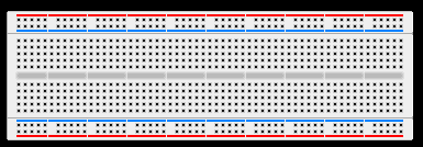
The Outer Edges marked in red and blue are for your "power rails" - ie how power is provided to the circuit. For most guitar pedals or guitar related circuits, this is a simple 9 volt battery, though I do a lot of my prototyping using an AC Adapter instead.
The inside section is usually split by a "trench" in the middle - this is to split the board in half for use with DIP (Dual In-Line Package) Integrated Circuits (or Microchips as they are usually referred to), so each pin has it's own group of 5 or so pinholes you can attach components to. A lot of these are setup like a grid, but I typically don't use that feature.
Board sizes can range from tiny 2.5"x2.5" boards, all the way to huge developer boards meant for making some pretty complex electronics. I usually run the size above, though my current setup has 3 of these double-sided taped inside a pedal enclosure so I can test my devices in real-time while I work on them.
Veroboard vs. Prototyping Board vs. Tagboard vs. Veroboard vs. PCBs vs. Artistic Circuitry
These are the construction methods of making a permanant fixture of a circuit.
Tagboard - Tagboard is classically what was used in a lot of classic Tube Amps from all the big names, such as Fender, Marshall, Hiwatt, Orange, and what have you. If it's from teh 1950's-1980's and it's a tube amplifier, it probably uses/used this construction at one point. My SkullFuzz Pedal is a tagboard wired pedal (it uses a very small five lug tagboard in the middle of the box to solder everything to) - so it is a legit method for Pedals.
Prototyping Board - Prototyping Board is usually a specialized purpose board intended for making prototype circuits. It has pre-made/pre-set provisions fr things like the power rails or grounds. It's a bit like a solder-version of a breadboard, and a lot of breadboard projects can be transferred to this type of board. Sometimes these are also called veroboards, but they require knowing where to cut the traces on the bottom to break continunity between components that should not be linked up to that point.
Veroboard - Veroboard is just a piece of PCB with holes drilled all over in it, and each hole has a small, circular solder pad attached, each pad isolated from the others. With these kinds of board. The idea is to solder your components and make your own traces by drag-soldering solder between the traces that should be attached to each other. These are one of hte most popular methods to make your own pedals as it does not requite gerber files, caustic chemicals, or sending your design to a manufacturer to have them made.
Home Made PCBs - This is where you buy some "copper clad board" and etch it yourself. The classic method is to use some form of a pen, marker, printed out and ironed on solder mask, and apply it to the copper side(s) of the board. Then drop the board in some Ferric Chloride with some heat and agitation to wipe away the copper from the places uncovered by the ink/toner. That's the method I've been using. Another method is to cut through the edges of the mask using a laser, drill, CNC, or dremel. Another method is the "Chicago Style" construction where the board has isolated circles cut out and components are soldered to those. It can be tedious and difficult, but it works, and if it is done well, it can yield some pretty nice results.
Professionally Made PCB - This is where you use a program like KiCAD or some other EDA Software to maek some "Gerber Files" of your circuit board, to send into a production house like PCBWay or someother place like that, and then you get a "run" of your circuit boards made by them that look like production quality pieces.
Decorative Point-to-Point - A popular method in recent years is to forego the circuit board entirely, and instead, use pieces of wire lead from the components themselves to make traces in the open air. This leads toa circuit that, if executed cleanly, looks rather awesome. Almost all of the components are strategically wired with their leads bent at right angles, designed to come in contat with the components it's supposed to link up to. Problem is, this is not effective for more complex circuits. It's also time consuming, and can be very difficult to pull off cleanly if you don't carefully plan where components are being soldered.
How I got Into this myself....
So I got into the process of making my own effects and guitar circuits because I was in a band at the time called The Sweaty Vedders, a Seattle-based grunge rock cover band, and it was a real shift in style for me. Prior I was relying soley on Marshall-type crunch from a EL34 based tube amplifier, now I needed that grungy, dirty, fuzztone for certain things where the Marshally tone did not fit the mold, and I started looking at Fuzz Pedals. I did not want a one-trick pony though so when the band was done I could still be using it. I also did not want to pay $245 for something I could build using $15 in parts to make.
I had some prior experience wiring guitars, which is somewhat of a specialty for me. I knew how to read schematics just well enough to understand what was going on, and I understood enough about Electronics to be at worst *mildly dangerous* (to the components, not myself) with this sort of thing. So I went to Vetco in Bellevue, spent $90 on a stockpile of components and a couple other useful things, and began breadboarding my own Fuzz Pedal at home using some YouTube Videos as a springboard - the 7-minute Fuzz being the main one that got me started.
In the end, I wound up experimenting and making my own unique Fuzz Pedal that I was happy with and more than excited to try out. By the time the pedal was done, about 6 months later, I was ready to bring it into the band, where it served me well for about a year.
|