|
I have decided to revamp my Tech Pages on the Atari VCS/2600. These pages only deal with the original Atari VCS units sold between 1977, and 1992. I started doing my own repairs on these machines back in the 1990s when they were used, a dime a dozen, and could be treated more like a modern PC as far as modular assemblies. However, the dark truths about the VCS/2600s from the original run, is they are getting older, and you're going to see more problems with them as they get older, and those problems might throw people for a loop. THis is why I decided to revisit this topic, because I have not touched on it in almost 25-30 years. Luckily, these old things do hold up a lot better than people thought. You have to remember, these consoles came at a time when these were "for the kids", and as we know, little kids are awful to electronics. So a lot of people mistakenly throught a system was dead or a controller was unfixable, just because it was "used hard" or because they just don't know about electronics. I assume SOME electronics knowledge here.
DISCLAIMER:I lay no claim to be a electronics engineer, what you do to your Atari or choose to create for it is your own business, and of your own volition. CreepingNet and the webmaster assume no responsibility, liability, warranty, guarantee, or otherwise for your choice to carry out any actions you may choose to do after reading this page
Types of 2600 Console - Reprise
There are four major types of 2600 console, see the table below for each type, and their description...
"SIXER"
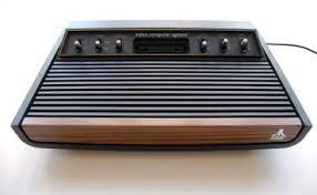     
| The sixer varieties of console include the Atari VCS and Sears Telegames VideoARcade "Heavy Sixer" and "Light Sixer". These consoels are easily told by the six brushed aluminum switches on the top panel flanking both sides of the cartridge slot.
The first ATari VCS Variant released was the "Heavy Sixer" (1977-1979). The Heavy Sixer is named such due to it's heavy weight (around 4-ish Pounds). These were produced in the USA Sunnyvale California Atari plant, giving them the nickname of "Sunnyvale" consoles, even though a later run of consoles were made at an unknown factory in Taiwan starting early-mid 1978 and ending once all the "Heavy Sixer" bottom plastic - it's most distiguishing part - was used up. This bottom plastic does not cover the edges of the front woodgrain, it features a higher "TM" mark than the later "Light Sixer" consoles, the top cover has 2 vents for speakers that never got used in the final production models, and the plastic is a different, a bit more flexible plastic about 1/2" thick. THese are also the most widely varied 2600's ranging from early models that only work on Channel 3 (no channel select switch, just 4 vents where the hole for it is usually found), and non-letter Serials, all the way up to units that basically have teh same guts as your average "Light Sixer". The channel select scenario can vary wildly with these. There are some Heavy Sixers without a channel select switch and no hole, some with a switch and a hole, some with no hole and a switch, and I've had mentions of a rare few that look like someone cut a hole at the factory by removing one of the bars from the bottom right side vent. In some markets, Heavy Sixers with only Channel 3 support were custom-modded by a local shop to work on Channel 4. THe only way to know is to experiment.
The Light Sixer was a cost-reduced version of the 2600 introduced in 1978 and ceased sale as late as 1981 - parallel with teh "four switch" variants somewhat. Earlier units have smaller switch holes, and the pointed bezel around the switches of the Heavy Sixer, though later variants got the flat switch bezels that carried over to the 4-switch in 1980. The initial internals were identical to the late era Heavy Sixer and likely had more changes later on. One of the most noticeable differences is the size of the oscillator crystal (the Heavies had HUGE ones). These, along with very late model HEavy Sixers, had a hole in the bottom with Channel A/B molded near it. You needed to stick something like a hibatchi skewer into the case to change the switch.
|
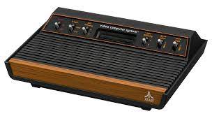
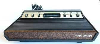
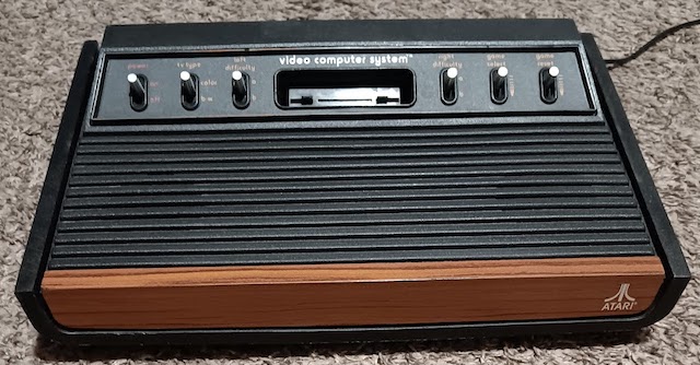
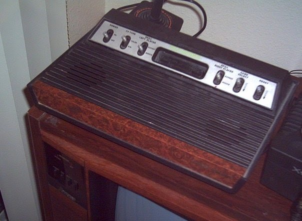
"FOUR SWITCH"
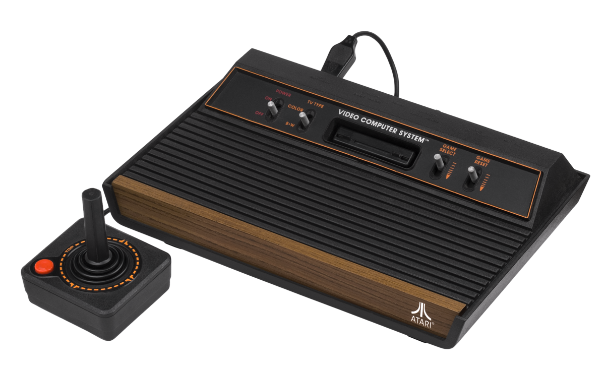  
| THe Four Switch line started in 1980 with the "Woody" 4-switch. These looked almost identical to a Light Sixer except the control bezel had only 4 switches, and the top cover had holes for the controller ports, power jack, channel select, and difficulty switches (hence only 4 switches in front) to the back top of the console (and molded and labeled in the top there). These units also changed the design to ONE circuit board, rather than two joined with a ribbon cable or FFC cable the way the Sixer series consoles were. The earlier motherboards had socketed RIOT, TIA, and 6507 chips, like the original Sixer consoles as well. All "RF Shields" were stamped 1mm thick metal with twist tabs to hold the halves together through the circuit board. Later models had the chips soldered, particularly the "Vader" Model.
The major technical change to the circuit itself was the removal of the CD4050 Hex Buffer/Inverter IC Chip that was in the "Sixer" series consoles. This was used to "Debounce" the fire button lines and clean-up/amplify some of the video signals (leading to a much more vivid color picture on the earlier systems). However, something about this chips presense in the circuit is the reason some official Atari 2600 wireless controlers are silent on these systems, but noisy on the Sixer variants to varying degrees.
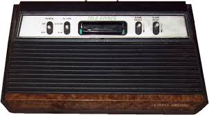
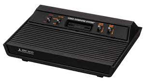
There were three variations of the Four Switch sold to the public: the Woody, which looked like the original 2600 like I said, except they only had 4 switches on the panel, the Sears Telegames 4-switch, which was just the woody in Sears regalia, and the "Vader" - which was the first version of the 2600 sold as the "2600". The woodgrain and orange border around the switches was omitted and the front Atari logo replaced with an "Atari 2600" logo on the left front panel, opposite of the Atari Fuji logo's location previously. These were called "Vader" because of their all-black color, like Darth Vader's outfit from Star Wars.
|
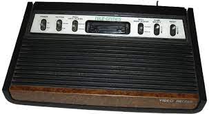
"2800"
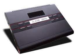 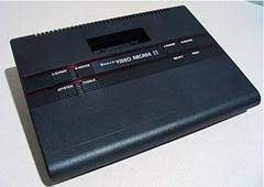
| The "2800" style consoles includes the JApanese Exclusive release known as the "Atari 2800" marketed in Japan by Namco, a business partner of Atari's (and creators of Pac-Man), and in America it was sold as the "Sears TeleGames Video Arcade II", both with special Joystick/Paddle hybrids that came one controller to connector, unlike the original Paddles which were two controllers to one connector. These are not as popular as the other versions on this page by far, as this was the end of Atari's association with Sears Roebuck and Co. to make them exclusive versions of Atari's creations.
These consoles look a lot like an Atari 7800, with a cartridge port, but they have push-buttons instead of switches for all the usual functions plus a "Paddle/Joystick" button used to activate the second pair of controller ports for 4 player paddle games such as "Warlords" or "Breakout".
|
"2600 J.R."
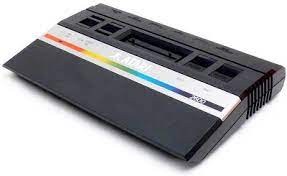 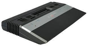 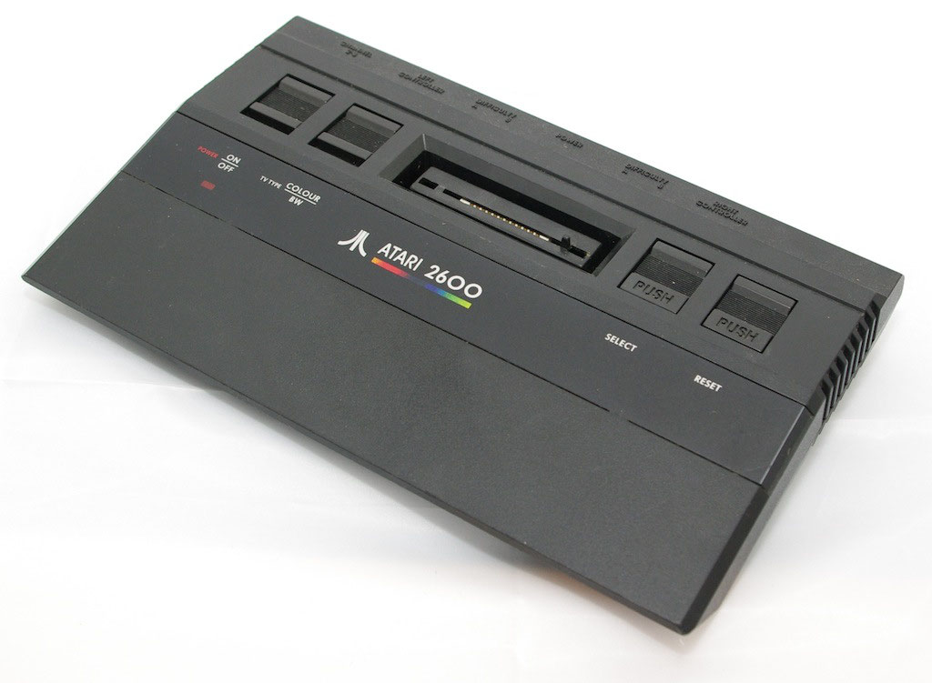
| The "2600" Junior series were a line of VHS-tape sized consoles released in 1986 as a "budget" option to Atari's product line which also included the 2600-compatible 7800 Pro-System. The 2600 was markteted notably under the tagline "The Fun Is Back for Under Fifty Bucks". These units came in four varities, Short Stripe, Long Stripe, Long STripe Holy grail, Black-Strip (Ireland), and Black-STrip Holy grail (Ireland Only). THe general style was an angular, small, all-black case with a typically stamped aluminum trim strip across the top with "ATari 2600" in the middle, a rainbow stripe underlining just the logo (short stripe), or the whole panel (long stripe). It also was the first and only version of the 2600's origianl run to have a power LED light on top.
These units also had a RCA jack in back for RF output, instead of a hard-wired cable plugged in on the inside of the case. The "Holy Grail" units are special units that instead of three discreet chips for the TIA, RIOT, and 6507, have one chip codenamed "PAM" (Atari named chips after **ahem** well endowed female Atari employees back then....it was a different time). The PAM Chip was a SOC version of the 2600, and has some incompatibility issues with certain games due to it's early VLSI design.
|
Why it's important to know this off-the-bat is so you know what's under the hood of whatever Atari system you are working on. While the 2600 in general, used very much the same circuit throughout it's lifetime, minor variations of said circuit do exist per the Atari Field Service Manual.
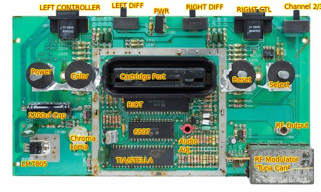
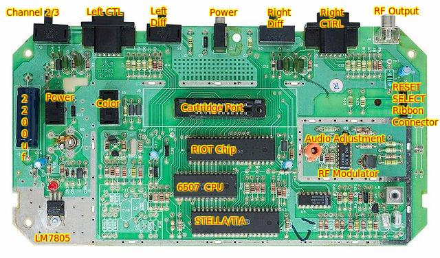
Adjustment Ports and Components of Note on the COnsole
Each "Variant" has specific components of focus. THis includes all the major switches and ports, as well as any internal jacks on some consoles (RF and in the case of the "Sixer" series units, a ribbon cable joining the switch/power board to the motherboard). Let's talk about these key components first before we see where they are on teh system.
- Power Jack - This is always going to be a 1/4" switched mono jack (Center positive) to take a 9 volt 1A AC Adaptor. The AC Adaptor (or Battery Eliminator as Atari called them in the 1970's as all the previous dedicated consoles could run on batteries as well as an adapter). You can make your own custom A/C adaptors to use out of orphans from a local thrift (what I do), or purchase new replacements that are likely better quality than the ATari Originals. I also have fixed the original adapters before with much success (my taiwanese 1978 Heavy Sixer's original PSU is one I Fixed).
- Controller Jacks - these are plastic, cheap variants of the standard DE/DB9 male jacks used for PC Serial ports. They solder directly to the board, and are best if they have index pins. I will talk about pinouts later when we get to controllers.
- DIfficulty Switches - these are located on the back of the Junior and 4-switch type consoles, while they are on the front panel of the "Sixer" and "2800" type consoles. Traditionally these controlled "handicaps" for the right or left player's controllers but in later games served additional functions such as changing menus, controllign a space ship, or toggling certain in-game features in general. These are typically Double Pole, Double Throw switches acting as a single pole, single throw.
- Channel 2/3 Switch - On the original sixers that had them, these were located on the bottom right side facing down (wood towards you) and labeled Channel A/B. Just because it has this hole does not mean a "sixer" has the switch though. The four switch relocated this to the back, not sure where it is on the 2800 style, but I know on the Junior it's in the back on the opposite side of it's location on a 4-switch. THis is typically a single pole, double throw switch as it's selecting from two points on the RF modulator for channels 2 and 3.
- Power Switch - Always the leftmost switch facing the front of the console. On teh 2800 it's a button. On the originals excep the Jr, it's a double pole, double throw, tall mount, long metal lever slide switch that behaves like a single pole, single throw switch. On the 2600 Junior, it's a single pole, single throw switch.
- Color/Black and White Switch - Just like the difficulty switches, this is a double pole, double throw switch acting as a single pole switch to pull the signal "low" when in the Black and White mode (by grounding off the signal). On the Jr is a single pole, double throw IIRc.
- Reset Switch - This is a momentary on, normally off lever switch or push button, it only needs to be single pole, single throw, but the original 2600 six and four switch models have double pole double throw (more on this excessive use of DPDT switches on the originals in a minute). It temporarily pulls the signal low to register a "Bit" to the console to tell it the switch has been pulled. This switch is used to start the game and is the furthest switch on the right on all units.
- Select Switch - This is a momentary on, normally off lever switch or push button similiar to the Reset Switch, but used to select game variations by pullign the signal low by grounding it off.
- Controller Joystick/Paddle - this is a button on the 2800 style units only that allows up to 4 controllers of their default style to be plugged into the Atari to allow for 4 player games. These likely are a Single Pole gounded=bit=0 (signal pulled low) type switch scenario not unlike the other switches on the Atari.
- 2200uf Capacitor - this is a filter capacitor used in ALL 2600's as a part of the power circuit that can go bad and need replaced if the unit is not getting stable power, or not getting power at all.
- LM7805 or LM78M05 - This is a Voltage Regulator IC (Integrated Circuit) that kicks the voltage from the AC Adaptor down from 9vdc (roughly) to a regulated 5vdc for all of the digital circuitry (read: COMPUTER) inside the Atari. I've seen both 7805 and 78M05 chips used, as only 500mA is needed in vintage applications. It's not uncommon to replace these though with a 1 Amp part though so that the Atari does not get "Starved" when using newer power-hungry devices such as wireless controllers, the AtariAge SaveKey, or ATariAge AtariVox modules (which can pull more than origianlly intended through the Atari's controller ports 5v line). 78M05 is 500mA while 7805 is 1A. The top is screwed to a heatsink with heat-conductive material between it and teh heat sink, and the 9v goes into the left side, ground is middle pin, and 5vdc comes out of the right side pin (label facing up).
- Cartridge Port - This is a 24 pin card-edge connector, not unlike those used by PC ISA Expansion cards, to connect your game cartridges to. It provides a physical interface between the TIA, RIOT, and 6507, and the game cartridge ROM(S). It's rare to need to replace these but I imagine the time can be coming for some as these connectors are nearing 50 years old - well past their MTBF (Mean Time Between Failure) rating.
- CHroma/Luma Adjustment (aka. Video Delay) - This adjusts the color (chroma/luma - chroma and luminance put together) of the Atari. It usually only needs a slight adjustment due to drifting component values, but if it's majorly off or can't be righted well, then there might be a need to replace some capacitors or other components to fix your color issues. That said, the Atari 2600 is a bit like a musical instrument in that I've never seen 2 2600's ever be exactly alike when it comes to color, giving each original console a little bit of a unique "Character" to it's appearance.
- Audio Adjustment Yoke - this is a tall pink, red, purple, or some other weird color "choke" in the middle of the motherboard adjusted with a hex wrench. To get the adjustment right, use Open Broadcaster STudio, a VU Meter, and an Atari game with a static music (like Pitfall II, E.T., or RAiders of the Lost Ark) and adjust it until the audio signal is strong, and clear. You usually want it at it's loudest pound and it will sound amazing.
- RF Modulator - This is that rectangular metal box on the switchboard or motherboard (on 2600 Jrs it's under a smaller cover) that generates a video signal detectable on a Analog TV set on channels 2, 3, or in the case of some very early modified Heavy Sixers, channel 4.
- RF Output - This is a standard RCA connector for an RCA style cable. Keep in mind not all variants of the 2600 have a hole in the board to let a long center-pin RCA cable through. The cables Atari used early on had a short pin for this reason. Newer cables had a longer pin, and the 2600 Jr. have a dedicated cable "hard wired" (ie. connected) inside.
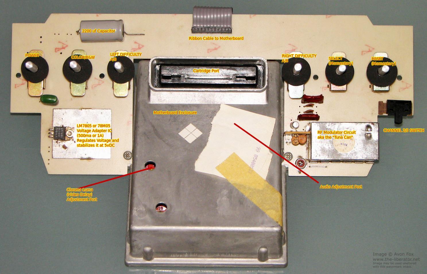
Inside Sixer with Shields Intact - The Sixer consoles are a bit more complex. A angled switchboard is screwed to the base of a large, cast zinc RF shield by two coarse metal screws. The switchboard is connected to the motherboard inside the metal box via a ribbon cable or a series of mid-gauge wires to a card edge or pin header. All six switches are tall leg Double Pole, Double Throw switches, with the furthest to the right (Reset and Select) being spring loaded and momentary (and normally off). THe Voltage Regulator either sticks out from the power board further up (early Heavy Sixers) and is clipped to a large metal heatsink, or it is installed sideways and screwed to large metal heatsink plate soldered to the ground bus of the switchboard. It's easiest to work on a Sixer by removing all of the guts like this as one big unit, first by removing the top (with 6 screws), pulling the top off, and if you need further access, remove the rest. However, it can be a pain to get the motherboard back inside the "can". Sometimes I use a game cartridge (official Atari cartridge preferred) to align the port with the hole in the RF shield. On the right side of the switchboard, there are some cases where there is no channel select switches (early Heavy Sixer). The most common issues I see with the switchboard is a bad 7805 Voltage Regulator, bad 2200uf cap, failing/cracked/cold solder joints where the ribbonc able connects to the motherboard on either end (the pin header on my Taiwan Heavy wasn't even fully sodlered leading to Adventure having random "Seasons", LOL), and of course, the switches. Luckily, switches are easy to clean/fix, and if open ended, REALLY easy to clean/fix. You should not have to replace them except in very rare cases (or when the switch tip is broken off).
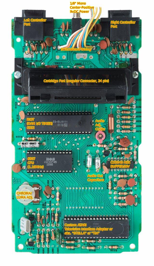
Six Switch Motherboard - The Six switch motherboard is it's own separate entity devoid of switches. Aside from the usual suspects, notice there's an extra ROM socket here - this was originally to have Combat or Air-Sea Battle built in (and thank god they didn't do that). IIRC, it was omitted because proper switching circuitry was not possible with the current design IIRC. I've seen some Sixer boards WITHOUT the ROM socket, and I've seen some light sixers with earlier Heavy Sixer motherboards (my Sears TElegames has the same revision and style of board as my Taiwan Heavy Sixer, which strangely has the same board as my high-school E-serial Sunnyvale that had a weird early switch board with channel select and a clip-on heatsink). Sixers can vary pretty wildly. This board was either from a 1978 Taiwan Heavy like mine, or a 1978-1982 Light like my Sears. The biggest problem areas I see on these are the occasional bad chip, or bad connections between the switcboard and motherboard necessitating either soldering of the wires, or replacing of the cabling system completley (especially those early Heavy Sixers with a PAPER FFC going between the two boards - my E-series Sunny had one). By far though, the biggest failure point is that power jack. That's why most 2600 Recap kits come with one. Sometimes that CD4050 chip goes bad too.
Four Switch Motherboard (with RF Sheilding Removed) - When Atari went to the four switch design in 1980, they omitted the CD4050 chip, and relocated the difficulty switches, and put everything on one board. Those ribbon cables were a big problem for some of the original sixer 2600 units. The four switch units were a little more reliable. However, they lost some of the vivid video quality of the original sixer units because of the loss of the Hex Inverter/Buffer chip's involvement in video signal cleanup/debounce. But it also reduced cost. The TRICKIEST part of this setup though, is getting the motherboard in and out of the Atari. there's now only 4 screws, 2 at an angle going through the motherboard and faceplate, and then two in front where the woodgrain/vader trim is. Problems I've encountered are bad power jacks, chips that need reseated, and once a mint Vader that had an Earring in the cartridge slot (!!). One thing that DOES suck about the Vaders is that the majority of them have the RIOT, TIA, and 6507 soldered directly to the board (REV14 and later boards). So these can be a REAL pain to replace or fix. I'm waiting for someone to "OpenTendo" the motherboard from these units for that reason, lol (hell, I might even do it).
2600 Jr Motherboard (with RF Sheilding Removed) - The 2600 Junior had the most extreme redesign. First off, there now a power LED added into the mix of power-circuit components (you can change the color on it if you want), the slide switches are now replaced with board-level soldered spdt slide switches that the visible switches slip on top of. The Reset and Select aree one of the biggest failure points on these because they use a mylar ribbon of contacts that fits FFC style into a card-edge connector on the right side of the motherboard. A newer fix is to solder some wires to those ports, and then put in physical contact switches for select and reset. Power jacks again are one of the big achilles heel on these. I'm tempted to pick up some cheap Jrs and fix em' as of late (to flip, maybe ONE to keep for the bedroom setup).
Now, here's things I tend to check on an Atari 2600 under some conditions, a traditional "Troubleshooting Chart" of easy to do at home repairs to your 2600 when it starts acting up.
| Issue
| potential causes
| Troubleshooting
|
| Atari is on but there's still static noise, or just a fully blue screen still as if it's not turned on.
| - Wrong Channel
- No Power to Atari
- Power-Circuit Issue
- Power Switch Issue
- Wrong CHannel - Make sure TV is on channel 2 or 3 (or 4 if Heavy Sixer with no channel switch if 3 doesn't work). If going through a VCR, make sure TV/Video switch is set to "VIDEO" and make sure the input is set to "VHF", and make sure the channel is set to Channel 2 or 3 matching the switch on the back/bottom, or to 4 if 3 does not work when using a Heavy Sixer
- No Power To Atari - Make sure outlet has power first, by plugging in a lamp or a fan or something else instantaneous. If the outlet is working, suspect the power adapter first. If you have a multitester, set it into the 10 volt range, plug in Adapter, and put the black lead on the sleeve, and red lead on the tip - it should measure between 9.0vDC and 14vdc - and make sure it's NOT NEGATIVE (ie -9.0vDC). If the adapter fails, try a different AC Adaptor in the 9vDC 1A range, if it passes, suspect the power jack. THere you can do one of two fixes. The easy one is to order a new 1/8" mono phono jack, desolder the old one, and replace it with the new one (Soldering iron required). The harder, "punk rock DIY" fix is to make a little tool like I did using a bent thin gauge (but sturdy) wire, and attempt to pull the pins down inside the connector. The cheap fix if you're feeling lucky is to re-flow the solder to the three pins on the motherboard.
- Power Switch Issue - It's not uncommon for the power switch on the oldest units to either get cracked solder joints from stress (40 years of angsty teens, cranky kids, or people with dirty hands turning the unit on and off has taken it's toll, LOL), dirty switches, or even the switches metal frame might have gotten a little bent and the contacts inside no longer make contact with the switch pads inside. Luckily, Atari switches on the sixer and four switch models are pretty easy to fix yourself (well...except Select and Reset but more on those later). So you may want to try cleaning the switches first with Deoxit (or similiar contact cleaner), and if that does not work, try reflowing the solder joints as they could be cracked or loose. In rare cases, the board may have cracked and you can bodge-wire the traces back together. Finding replacement switches in 2025 is a PITA.
|
|
| Atari Turns on and screen turns black but no video or two stripes at each side of the screen
| - Poor Cartridge Connection
- Inadequate Voltage
- Bad Chip
- Clean the cartridge port, make sure there's no debris in there (like someone's earring, LOL), one way to do this is to make your own port cleaning tool using a thin piece of cardboard, with some printer paper wrapped over the end (this is what I've used on all my cartridge based systems since day one), and then insert and remove it a handful of times, check the paper. If it's dirty, you'll see silver/black stripes on the paper, so then shift the paper around, and then repeat. I'm currently working out a way to re-bend the pins back inside the connector as well.
- Use a Multimeter and check the power adapter like #2 above, if the voltage to the adapter is good, then open up the Atari and check the LM7805 voltage adapter chip by putting the black on the center pin, and first checking the left pin for 9v, and the right pin for 5v. If unstable voltage, or voltage is too low, replace the 7805 chip. If the 7805 seems to have good voltage, unsolder one side of the 2200uf cap and test, most likely this could be bad as well.
- Get a 2nd, cheap Atari, or a good set of RIOT/TIA/6507 chips, and then swap each chip out one by one and see if it makes a difference. My Heavy Sixer's RIOT went out last year and the black screen with lines was one of the symptoms (as well as strange game behavior). Sometimes just reseating the chips can help, but if you swap and the problem dissappears (do this ONE AT A TIME, I REPEAT, ONE CHIP AT A TIME), then the chip is at fault.
|
|
| Atari Turns on but the Colors Keep Changing Around
| - The game is in Attract Mode (no fault)
- If it's a Sixer and it's in-game it could be a bad connection between the switchboard and motherboard
- Certain ATARI 2600 games (Combat, Air Sea Battle, Sky Diver, Golf, Miniature Golf, Breakout, Super Breakout, etc...) have an "attract mode" with a "screensaver" of sorts where the background, player sprites, score, and other on-screen elements randomly change colors every 5 or so seconds. this is normal behavior so nothing needs fixed, you need to hit reset to start a game (or read the manual).
- If it's a Sixer, and you're playing a game, say "Adventure", and suddenly it seems like the kingdom has a "spring/summer/fall/winter" cycle that's random, weird, and possibly somewhat creepy looking (with technicolor changing Dragons), then it COULD be you have a poor solder joint or poor cable connection between your switchboard and motherboard. The earliest Sixers had a "recall" for the paper FFC that connected the two, so you could fashion your own replacement cable system using modern connectors and FFC, or wires with a pin header on the switchboard like a later Sixer. Or you could just do what I did and reflow the cables on the motherboard and connector on the switchboard. That's what I did and it fixed the ole' Taiwan Heavy up.
|
|
| Atari Turns on But Select/Reset/Difficulty/Color switch don't do anything.
| - The switch in question does nothing in this particular game (particularly in the case of color/b&w, and the two difficulty switches, in some games, they have no function)
- Issue with the Switch
- Bad Membrane (Jr)
- Read the Manual for the Game in Question, if you don't have one, look it up on the internet. I know for a fact games like E.T., Raiders of the Lost Ark, Dig Dug, and some others don't use the difficulty switches, but if it's a game like Starmaster (which uses these switches for the menu) or Adventure (which uses these switches for color/b&w pallet change, Dragon repelled by sword for example), then the switches might need cleaned and/or a reflow of solder to work.
- If the switch is not working, and it should, then I would try spraying them with DeOxit and re-flowing them with Solder first before anything else. Remember, some of these have been soldered here for 40-50 years and might just need the lifetime stress of angry kids losing and dirty fingered kids spreading their cheeto dust into the contacts. Failing that, take apart the switch, or replace the switch (easier on 4 switch and later).
- Sometimes the Select/Reset Membrane keypad for the Select/REset switches on a 2600 Jr goes bad. There is a mod option using micro-size, SMD, tactile push buttons to replace this age-issue prone feature.
|
|
| Atari Turns on, But Game Exhibits Odd Behavior (ie. lots of Sheep in Stampede, weird sprite and playfield anomalies and blinking in Combat, "Ninja Harry" without "Frying" the console, Adventure assets inverted or misplaced, certain games refuse to run altoghter like M*A*S*H or Ms. Pac-Man)
| Potentially a Bad RIOT Chip could be the culprit. This chip is okay to go bad (it's the TIA that REALLY sucks to replace as it's a custom Atari chip). Usually it indicates a problem with the RAM (which is a part of the RIOT - as RIOT Stands for RAM, I/O, Timer), which can go bad after 30-50 years, so not unusual.
| Replace the RiOT CHIP. This is part number MOS/Synertek/AMI/etc. 6532 C010750. It doesn't take much RAM to be bad for a 2600 to act funky. Honestly, I kept my bad one because the effects are kind of funny and fun to mess with on rare occasion.
|
| Audio Sounds Faint, Distorted, or quiet
| Could be that the audio choke needs adjusted. It could also be caused by bad components such as capacitors behind it, but chances are in 40 years those values may still be usable, they just "Drifted".
| Start out by using a VU meter or your ears (if you're skilled at that like me) to adjust the Audio Choke and get it in the ballpark at least. I usually use the VU meter in OBS to get the audio tweaked correctly.
|
| Colors all Wrong
| Could be your CHroma/Video Delay adjustment needs adjusted, this is the flat-head trimpot located on the motherboard on the lower left-hand side
| Turn the pot left or right just a little bit until the colors look right. I usually use Pitfall for a Reference, but it's best practice to try across several games including a running session of Combat, Solaris, Warlords, and maybe one of the Breakout games. I find I can get it REALLY nicely tuned if I try across a few different games. If you can't get it right 100%, then you need to maybe replace a faulty capacitor or other component.
|
Atari 2600's are a lot like owning a vintage Carburated car, some adjustment may ne necessary and sometime a rebuild of the system is in order. Care and attention to it periodically is a good thing. That said, a well taken care of unit will last a lifetime it seems (only real concern being that blasted TIA/STELLA chip).
Controller Tech
There were a bunch of different controllers made for the VCS, I'm going to start out by mentioning that that is one of the more alluring qualities of the system, but here we are going to dive DEEPER into the controllers than usual. First off, we are going to have schematics posted, then we're going to talk about further things, including the trials, tribulations, and ideas of putting all these in ONE unit (and even some of my own controller ideas).
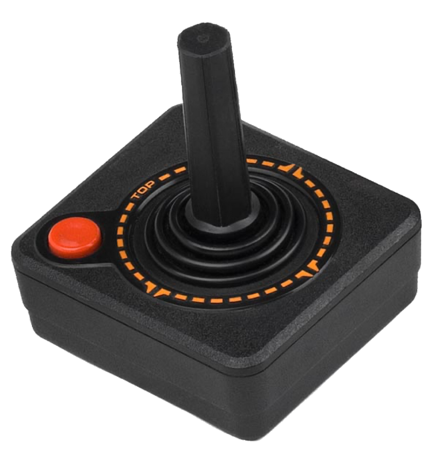
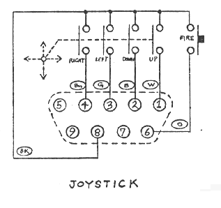
Joysticks (CX-10 & CX-40)
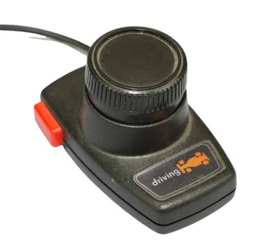
| Driving (CX-20)
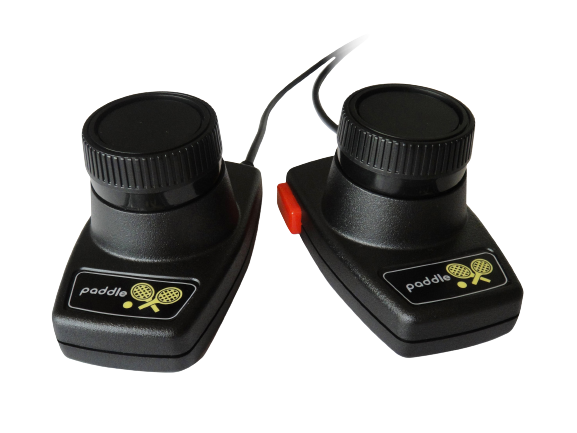
| Paddles (CX-30)
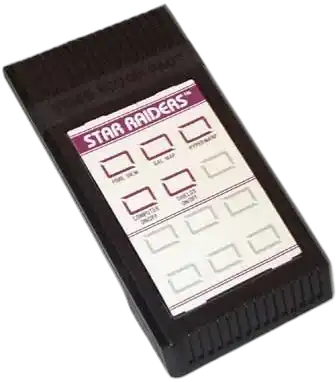
| Touchpads (CX-50, CX-24, Star Raiders)
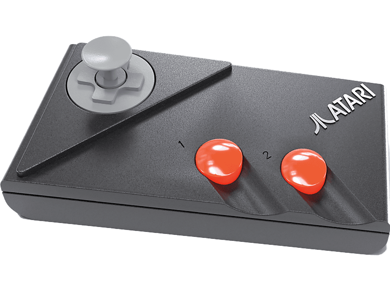
| 2-Button Gamepad (CX-78)
|
| 
| 
| 
| 
|
| 
| 
| 
| 
|
| Pretty Much All Games Except Indy 500, the Breakouts, Warlords, Astroblast, etc.
| Indy 500 only, also works with Homebrew "Zombie Chase"
| Most of the Ball & Paddle Games (Video Olympics, Breakouts, Warlords), Night Driver, Astroblast, Kaboom...you know the drill
| BASIC Programming, Star Raiders, some of the Sesame Street Titles
| Pretty much anything a Joystick was made for, also used for some Homebrews, includin at least one I recall used the 2nd button
|
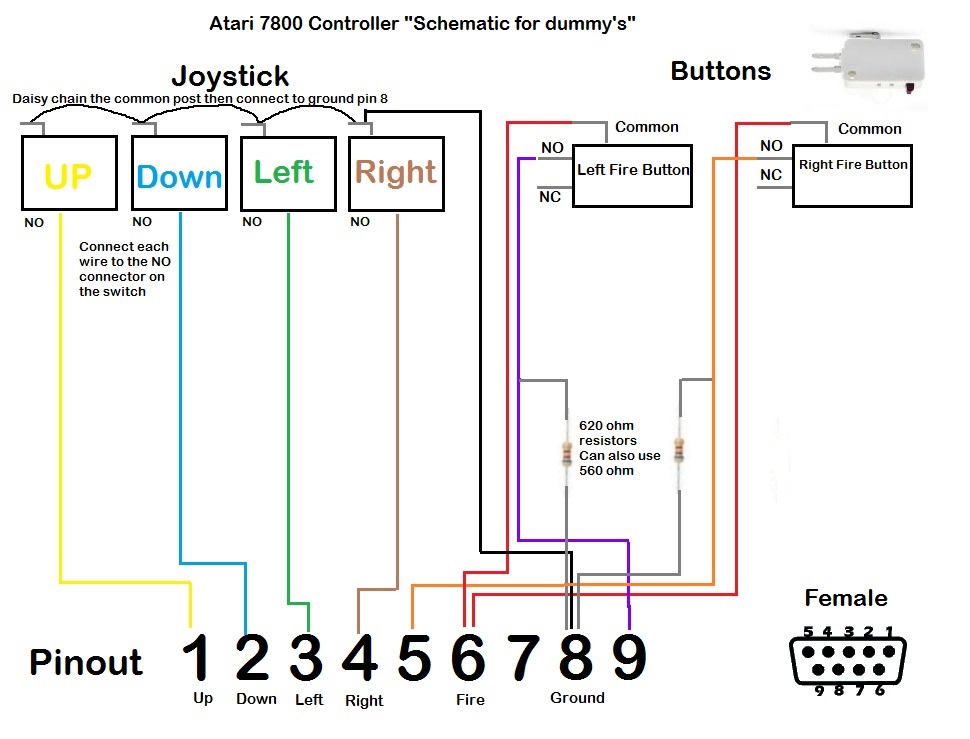
| Basically, the data lines for Left, Right, Up, and Down + Fire "go low" (short to ground) to activate their function. Pretty basic and easy to do. YOu can even make your own purchasing a replacement cable and either wiring up to a pre-existing joystick, or making your own parts and building your own even!
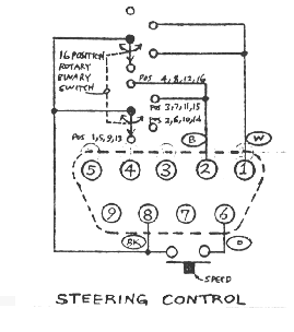
| A sixteen position encoder feeds digital data in 0/1/0 pulses on the correct wires at the correct time. I will do more "recon" on the wires. The fire button works the same as the Joystick by going low when the button is pressed (by shorting to ground)
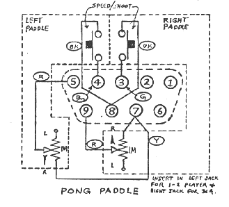
| Paddles work by feeding a signal to ground through the analog lines on the controller, and they come two to a pair - basically, varying voltage measured by the Atari to determine paddle position. It uses the left and right data lines for the left and right Paddle buttons.
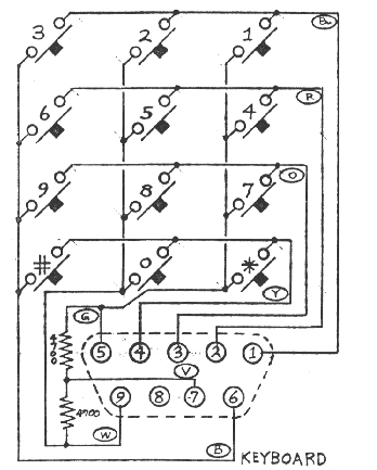
| This is a "Switch Matrix", It's done by connecting all different combinations to buttons on the pads for functionality. It does not give support for a full keyboard, but it provides just enough control to be useful for certain programs. I believe the resistors act as pull-downs or pull-ups, but I have not fully learned that part of electronics yet.
| The CX-78 is basically just the regular Joystick + one button that connects to pin 9 (Paddle A's analog line basically). By grounding that out, it gives 2 button support to the controller
|
With that out of the way, let's talk about the controller port pinouts themselves. THis is pretty much the closest thing the console games industry ever had to a "Standard" for video game controllers, which kinda' died out with the 1980's. Almost EVERYTHING used this standard including the Atari 2600, Atari 400/800, Intellivision, Colecovision, Atari 7800, COmmodore computers, Amiga.....it's wild. I remember going into a computer shop in 1989 (where I bough my first copy of California Games for the 2600 actually!), and seeing TONS of controllers there with this pinout, like a Clear flight stick with this pinout (probably analog), I even think they had some late editions of those colorful Joysticks everyone talks crap about.
Below are the pinouts for the actual ports and what they do.
| 1
| Joystick Up
|
| 2
| Joystick Down
|
| 3
| Joystick Left
|
| 4
| Joystick Right
|
| 5
| 2nd Paddle Analog Line
|
| 6
| Joystick/Driving Fire Button
|
| 7
| +5v
|
| 8
| Ground
|
| 9
| 1st Paddle Analog Line/2nd Button on Gamepad
|
My Own Ideas for Controllers
Raiders of the Lost Ark Gamepad - Raiders of the Lost Ark is an awesome game for the 2600, but it's more complex than the default controllers can allow for. So I came up with a cool idea for a controller to make this game less of a nightmare, and more efficient. Basically, we'd make an Atari Gamepad with 2 DB-9 female plugs on the end, one wired like a regular Joystick, and another one that only has wiring for left, right, and a second button for "drop". The idea is that you'd only need ONE controller in your hand, and be able to utilize the secondary functions along the top of the controls.
Atari 2600 Remote Control - Another annoying thing about the ORIGINAL systems, is some of us have to get up and hit reset all the time, and pressing "Fire" to launch the game was not a standard in 2600 games until about 1982 (and never was on Activision releases). Since the switches only really do something in ONE position, a cool idea would be a remote control that allows remote control of the VCS from a distance. I have two ideas on this, the cool one would be micro-sized actuators that could push the switches from inside the case, wired to their own electronically independant circuit that feeds off the power supply and uses an Infared sensor on an FFC that sticks out from the front of the case somewhere (like in front of the woodgrain. This would be AWESOME because then the switches would reflect their actual settings, and there's not a way to break the functionality by having the switch in the "low" position (or up in the case of power). The other idea would do this by using some chips like a CD4066 (quad switch chip) to activate the switches from BEHIND by soldering leads to the solder pads and then to the control board - same Infared situation, but if the switches were already in the "Closed" or "low" position, then the controller would be rendered useless because there's no way to open circuit on something that's already mechanically closed on the other side.
Enhanced Driving Controller - Basically, one of those combinations of two pre-existing controllers for enhanced functionality. This would be a cool one for say..."Hard DRvin'" on the 7800 with full arcade features, or even something like that on the 2600. How it would work is the driving controller paddle would now be a full steering wheel, the gas would be "fire" on the left controller, brake would be "fire" on the right controller, the right joystick lines would be tied to a shifter mechanism allowing for a five speed with reverse (ie up+left = 1st, down+left = 2nd, up = 3rd, down = 4th, up + right =5th, down + right = reverse, and all other positions = neutral). So you'd have a full on driving controller of this type, and what's cool is being standard, it probably could be reworked for the C64 or Tandy CoCo and other vintage computers that use Atari standard game ports.
|