GUITAR ELECTRONICS EXPLAINED A Huge Page on How To Modify, Build, and Tweak Guitar Wiring
Okay, so this is my catch-all page for electronics on guitars, probably going to be the longest page in the tech section because, if not already obvious, I've been modifying, designing, and making my own guitar circuits since the late 1990's, and therefore, I'm very experienced and skilled at it.
Tools & Equipment
of course, you can't do any of this stuff without the bare minimum of tools - which for me is a screwdriver and a soldering iron, and some solder. Yeah, I'm that nutty guy who uses his "gender gap" as a make-shift wire stripper sometimes....don't do that, not everyone has enamel that probably should be studied by 3M for it's resiliancy properties. So here's a rundown of the equipment I use/have used in the past for this kind of task to let you know what it's used for.
NAME PICTURE
DESCRIPTION
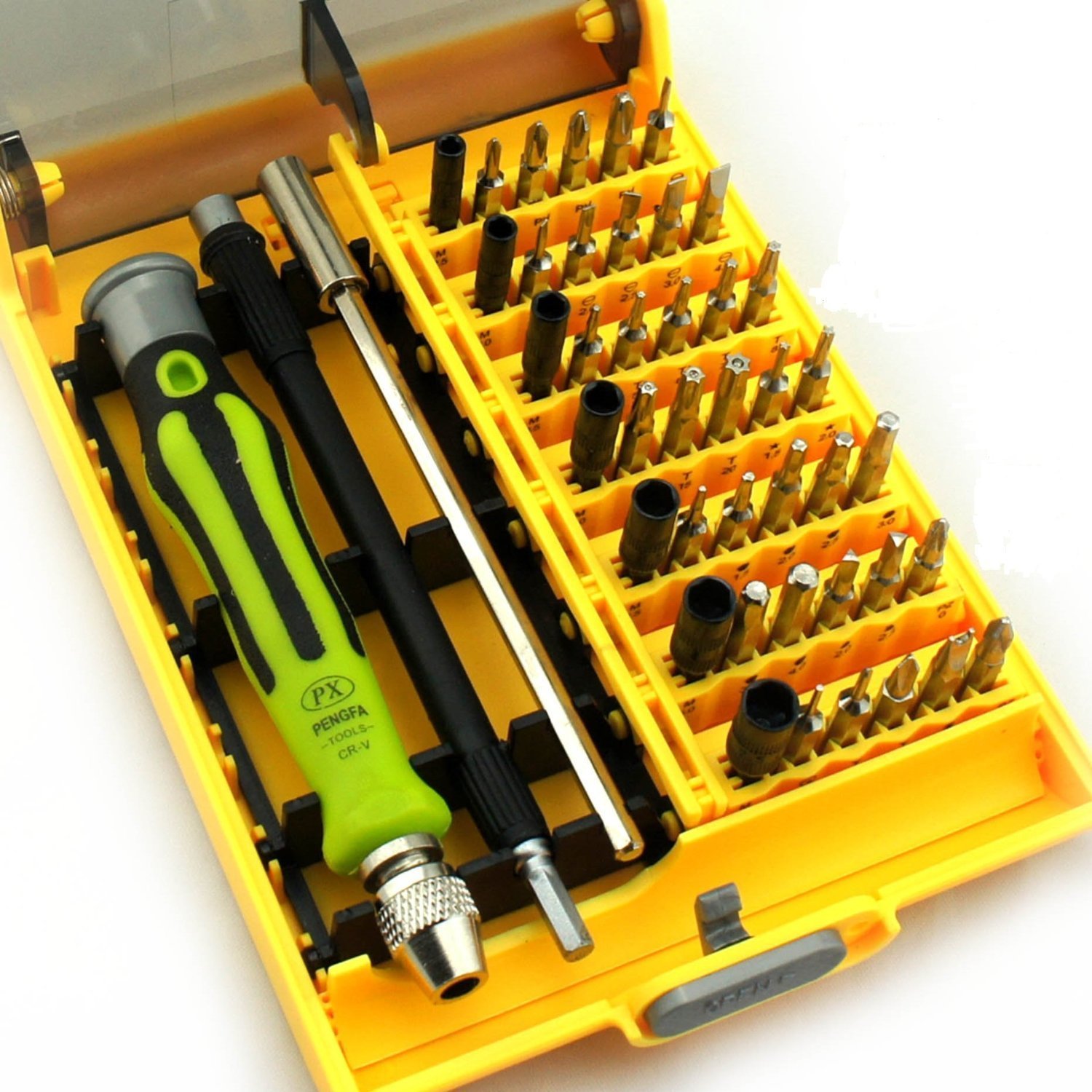
Screwdriver Set/Nut Drivers
First and foremost, we need to get into the darned things we are working on. On most electric guitars, philips and flat-head screws of smaller sizes are the most used. Though it also helps to have hex heads and torx heads to use for other purposes, including those outside of electronics. Even without a fancy kit like this, you're more than adequatley equipped with a basic, medium sized philips and flat-head.
Another unspoken use of these, in lieu of soldering probes and whatnot (those little pokers and chisels that come with cheap soldering sets), screwdrivers work GREAT in a pinch, to a point that's what I use most of the time these days for things like holding wires in place while I soak em' into a blob of solder on a control pot for example.
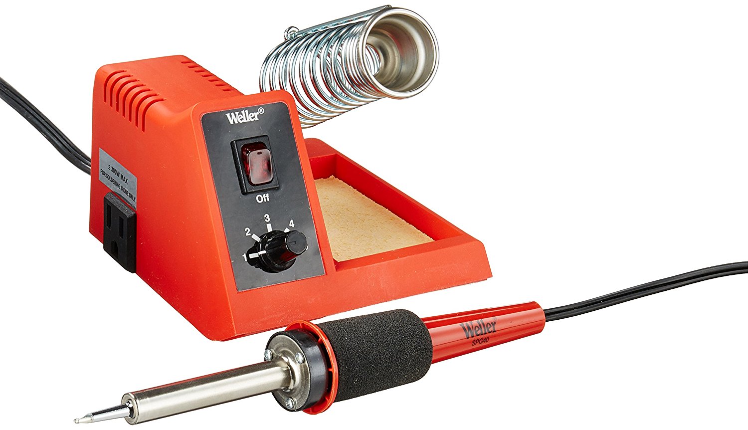
Soldering Iron
To the left is the exact soldering iron I use actually, a Weller with multi-temperature fine tip, and a sponge. There's probably much nicer units out there now, but I'm pretty happy with this unit and have been using it for over 10 years. What a soldering iron does is heats up hot enough to melt solder to make electrical connections. You usually tin the tip with solder, wick off the excess using the sponge dampened with water, and try not to leave it on too long or it'll burn out the tip of it.
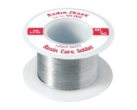
Solder
For this kind of work, you use 60/40 Rosin Core solder - NOT plumbing solder, not Jewelry Solder, but solder intended for Electronics. The stuff I prefer to use is finely extruded stuff like this, so that I can get pinpoint accuracy. remember, we are soldering TINY things here, not a giant copper pipe, so we want our tools to match the size. The solder you want to use is between the thickness of a .048 gauge low-E string (gauge code 16), to the the gauge of a G string (.028, code 22). This is small enough to melt fast and hot enough to give a good connection. That said, I must know my stuff well if I'm carrying a lot of 25 year old solder joints in my 86' Kramer Focus 3000 I did at 17.
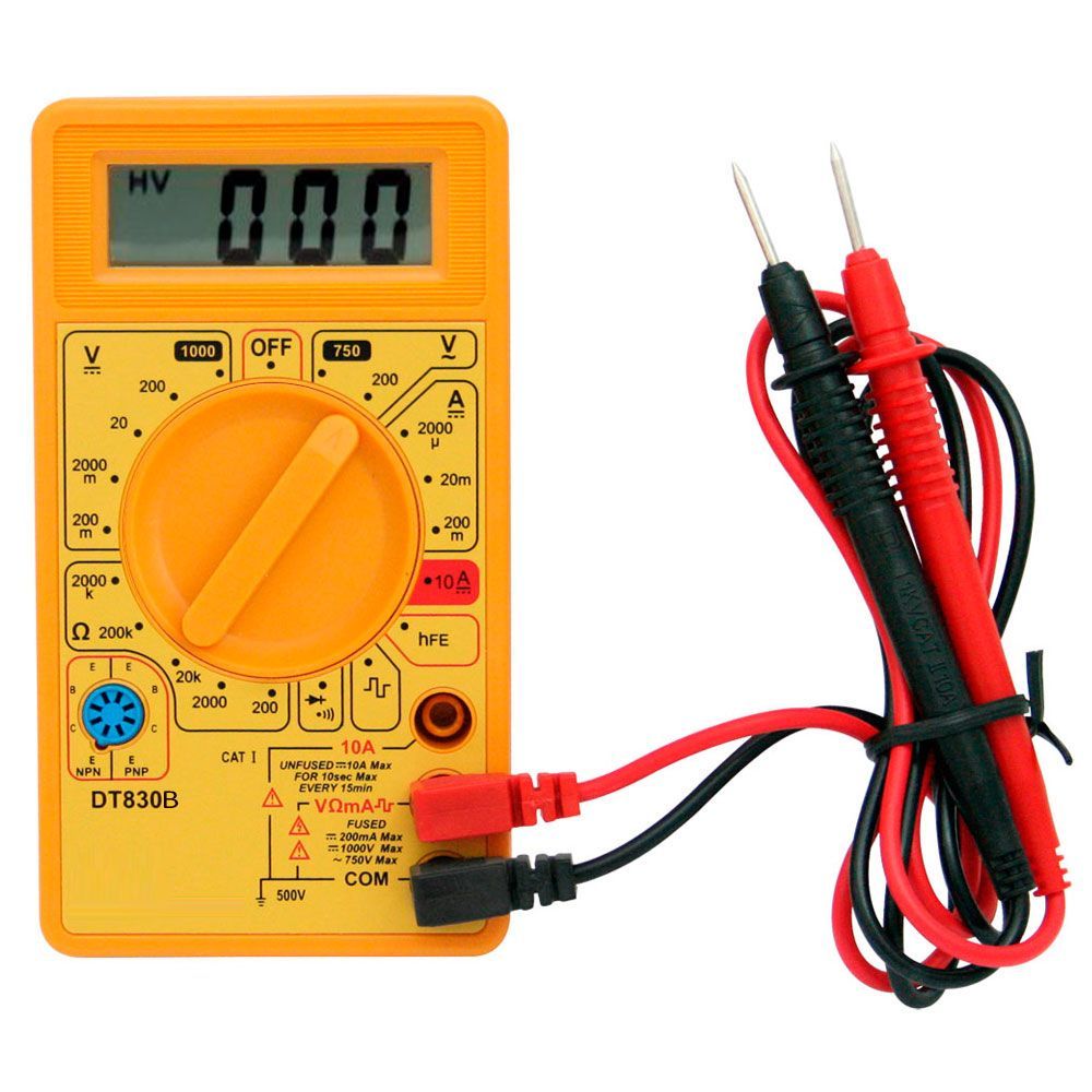
Voltohmeter/Multimeter
So, if you've ever read pickup ohms readings at places like Seymour Duncan or DiMarzio's websites - and elsewhere - and wondered where they get these crazy numbers like "16K" or "6.4K Ohms" - well, here's the tool you use to do that - a multimeter, sometimes referred to by old guys as a "Voltohmeter". Voltohmeter generally refers to the older analog units with the needle that we used to see back in the day (and what I started out using in high school). The three most commonly used settings on the dial in guitar circuits will be the short-test/is-this-connected setting, the 20K Ohms Resistance setting, and then the 20vDC scale for testing the 9 volts that came out of guitars with various gizmos like active pickups and sustainers installed in them.
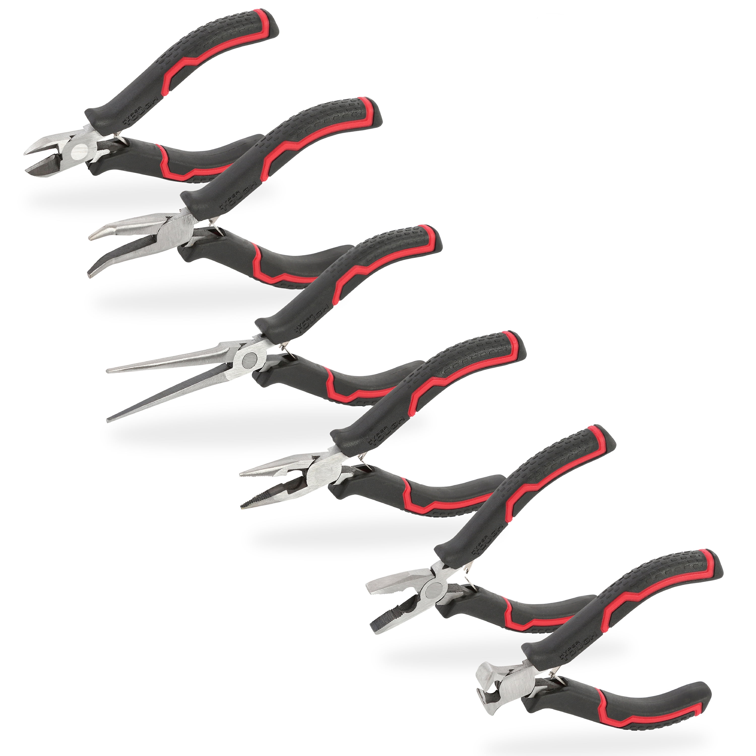
Pliers
You'll need pliers for a few things. First off, unbolting things like potentiometers, switches, and other things that use nuts to attach to pickguards or the bodies of guitars. Secondly, needle-nosed pliers are another holding mechanism and also useful for bending wires in the right direction, or working with tiny wires in tight spots that you can't grip easily with tweezers, and even bending tiny contacts without getting pricked. Also, many of these sets come with wire cutters, or have a wire-cutters built into them. Sometimes useful if you're being a total dolt like me and forgetting where you put down the wire-cutters mid rewire of some project, and need em' a second a go.
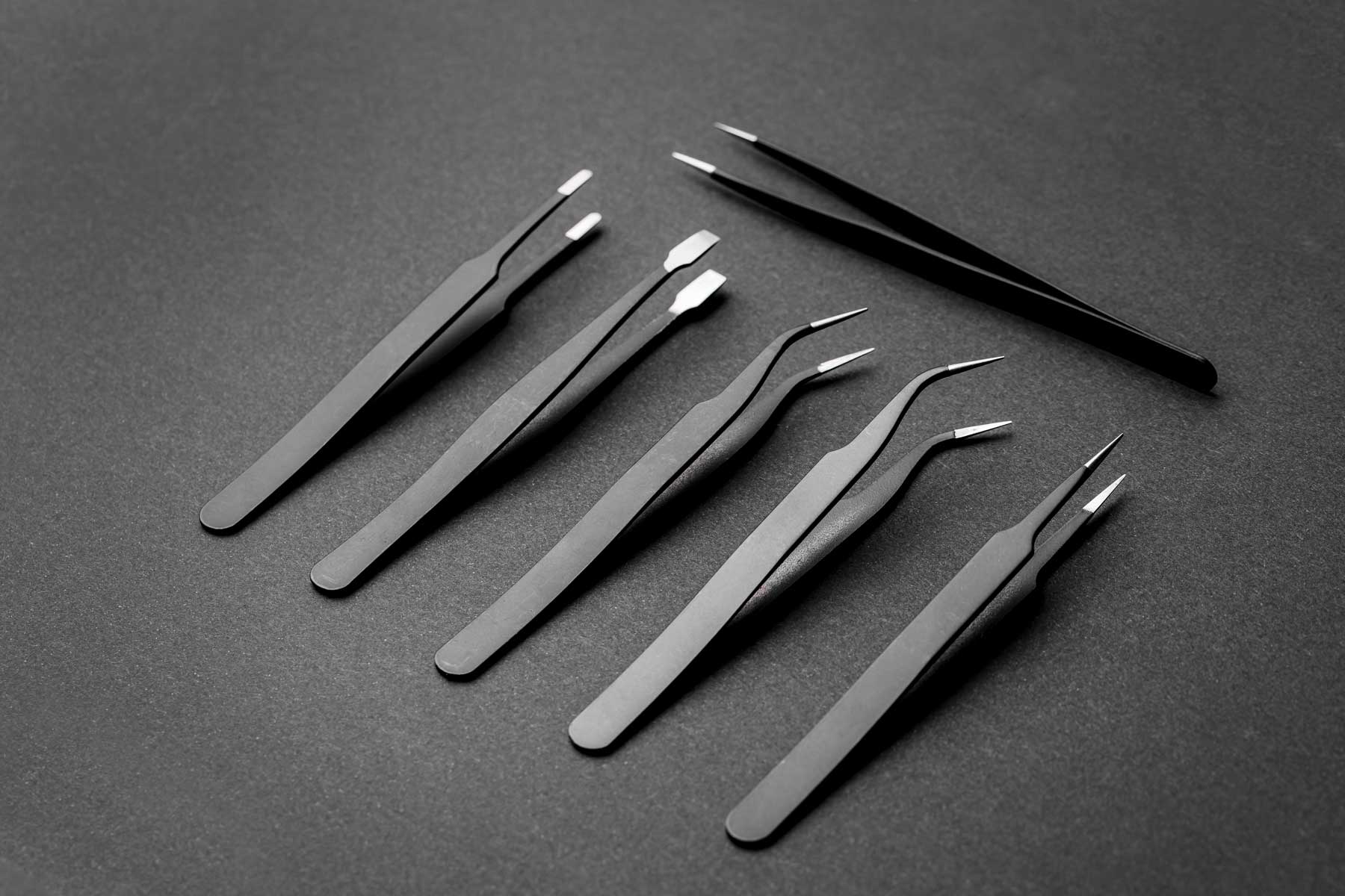
tweezers
Sometimes a pliars is just overkill. These are better for things like, holding onto tiny capacitors and resisors when soldering to pots, holding wires near their connections when soldering to tiny lugs on pickup selectors and mini-toggle switches, and even the ones that clamp down by default work great as a little heatsink for heat sensitive components.
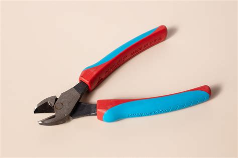
Wire Cutters
While the wire cutters on some pliers are nice, I tend to prefer this type that's much nicer to work with and has an easier time cutting. That said, personally, I use a set of mini-wire-cutters from an old Radio Shack PC repair kit that I had (why anyone would need wire-cutters fixing a computer after the 1980's beats me), and they work great. But these would probably be nicer.
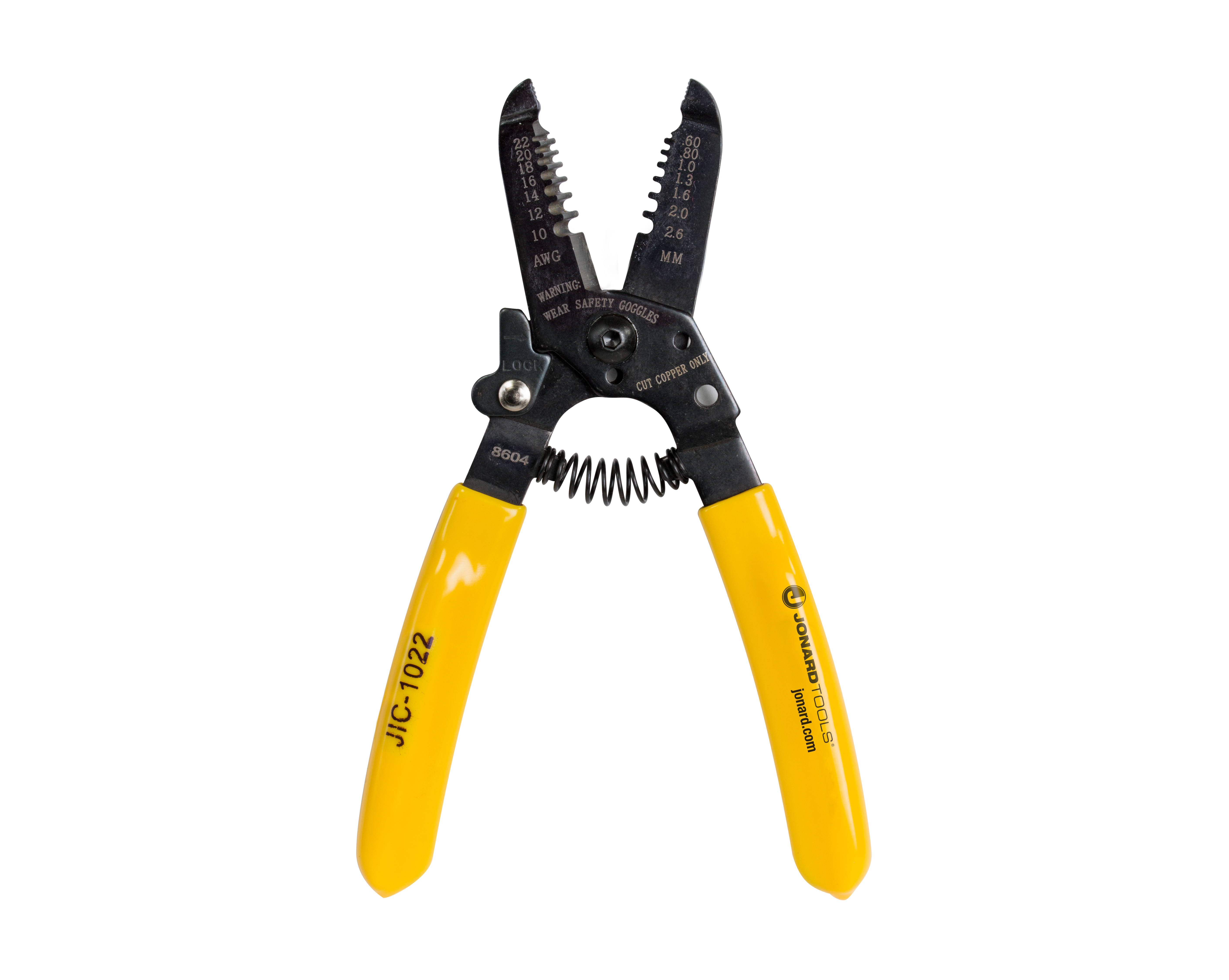
Wire Stripper
Like I said, I've used my teeth, some people use a razor blade or a pocketknife (which I've also done), or a box cutter, but the proper way to do it is to use one of these. Basically, it has a series of blades that surround the PVC insulation on the outside of a wire, and then you spin it around to cut the insulation, and then pull away from the end of the wire to expose the wire inside. These also often have wire cutters and even crimpers built in. Mine looks like hell, because I use it on my car and computer projects just as much as I do guitar stuff.
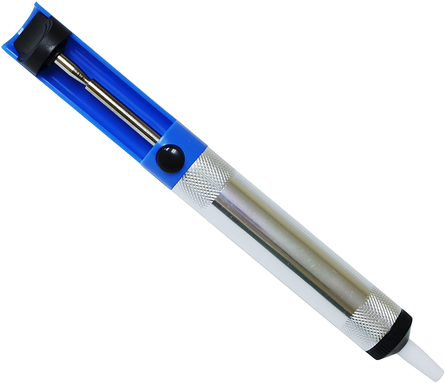
Desoldering Pump
This is one way to remove solder off of components and circuit boards (though I have more luck with circuit boards with this method than discreet components as used on most guitars). What a Desoldering Pump is, is a air-pump that you press down a plunger in back, and then heat up the solder, put the head near the solder, and press the button to quickly suck the solder off the joint.
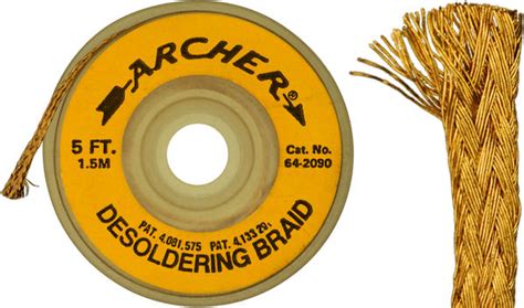
Desoldering Braid
This is the other way to remove Solder from components and wires, Desoldering braid, which is basically a mesh of thin copper wire that soaks up the molten solder, and then you cut off the used section and throw it away. Not as eco-friendly as the pump is, but a lot easier to use for people not used to double-fisting soldering devices.
Flux
Flux is used to help solder adhere to components and connections, and clean them at the same time. A lot of solder has rosin core in it to help with this, but flux REALLY helps. It becomes more important through as we move to things like circuit boards as it helps isolate solder to individual pads and whatnot.
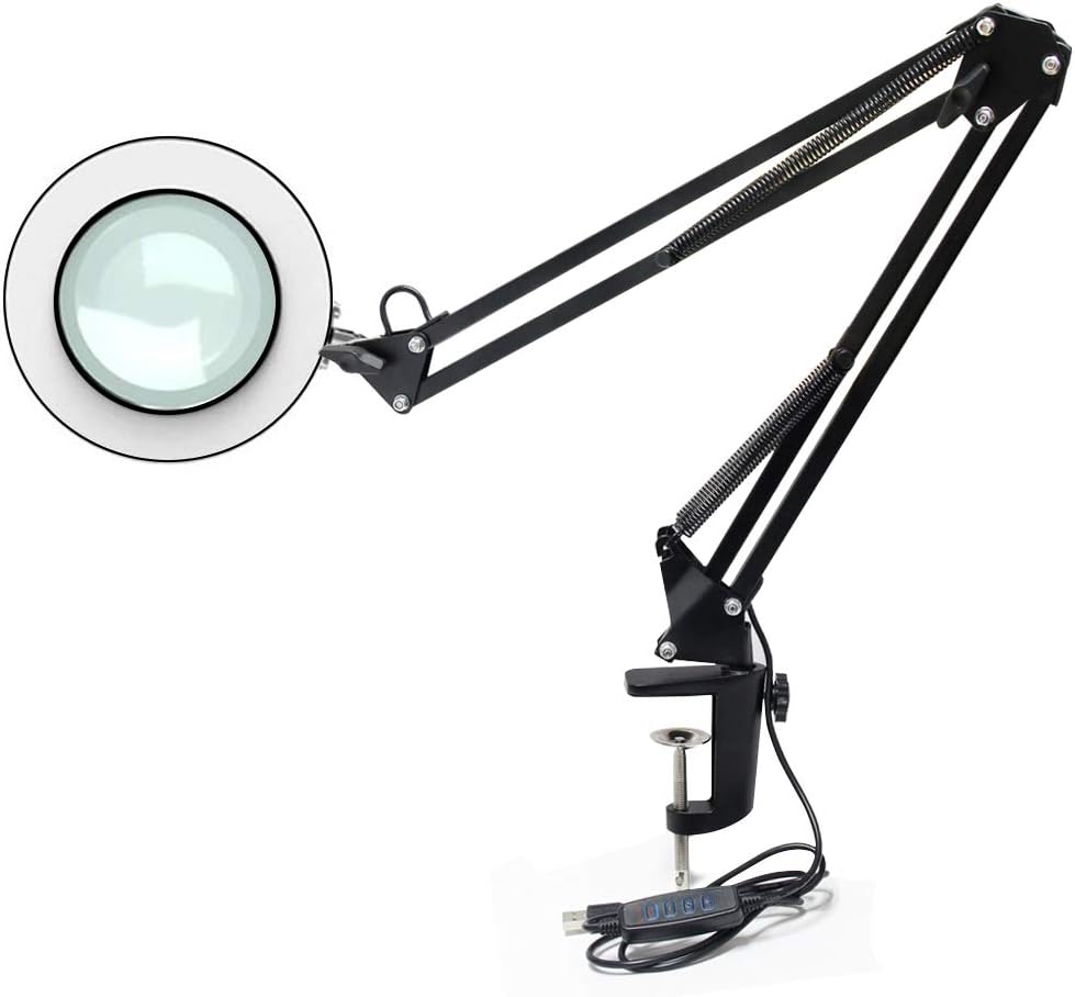
Magnifying Desk Lamp
One thing that really helps me is this lamp, which I use all the time now, especially since I'm getting older and my eyes are not what they once were. This is really good for getting up-close and personal with solder joints while soldering without having to really set your mane on fire to do so! It also helps see the details of your wiring, which can be really really important in the realm of guitar electronics, especially when you're cramming a NASA battleship worth of stuff inside a Strat!
So hopefully that sheds some light on the tools that I use for this stuff, and how they are used and why. You also can see it crosses with my other activities quite a lot. I've been threatening work that I'll bring the soldeirng iron in for years now - mostly due to slow OEM's not fixing stuff I know I can fix with a soldering iron....so yeah. This stuff is useful no matter WHAT you are into working on.
Components I Use in Guitars (and what they do)
Now, i'll go over what these components do in more detail, but this is a chance for those of you with SOME experience to understand their role in the circuit of a GUITAR. Since this is the most basic electronics page on the entire website (yeah, we're doing game consoles, TVs, and Computers, and even automobiles here too).
NAME PICTURE
DESCRIPTION
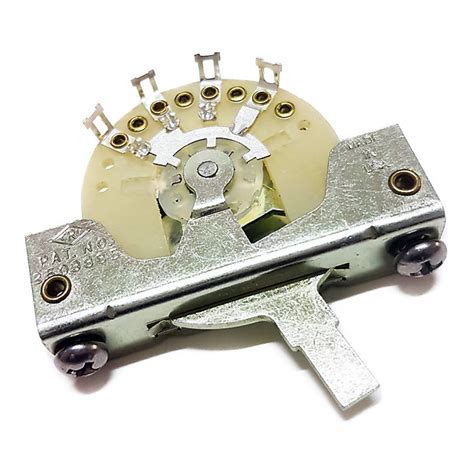
Blade Switches
Now, I'm sure you're looking at this and thinking it looks like some kind of cybernetic paper-wasp nest, but this is what the entire assembly of your average Fender-style 3-way or 5-way selector switch looks like, well, the vintage version anyway. Blade systems typically have eight contacts, 2 common contacts that are always active, and then three more that are either active one-at-a-time individually in all three positions, or alone or in pairs with the nearest pin next to it on a 5-way switch. 3-Way switches are used in Telecasters and 2 pickup strats, and the like, while 5-ways are typically used in 3-pickup guitars. There are variants now by FreeWAY that have 10 positions by tilting the switch on it's axis for five more selection options.
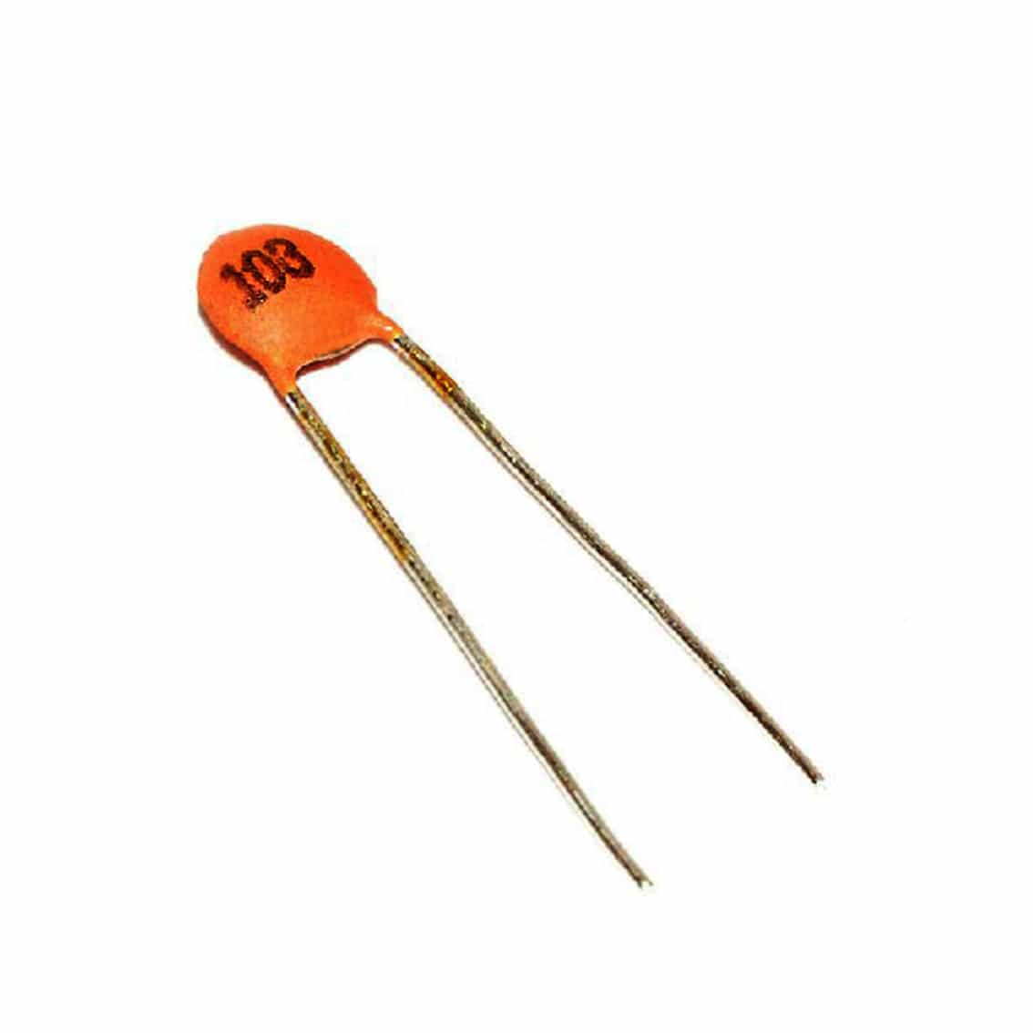
Capacitors
Capacitors often look like the "ceramic" kind to the left, or little "chiclets" that are brown, green, yellow, or red. Some of them - not used in guitars (typically at least) are the little ones that look like Soda Cans (Electrolytic). What a capacitor does, is fills up with current to a certain capacitance, and when once it reaches capacity, it dumps that capacity off. They're basically mini-batteries. Most often, capacitors are used for filtering in electronic circuits, which in the case of the guitar itself - filtering out high or low frequencies (strangle Switches and tone controls). I usually just use these cheap ceramic ones myself, though some vintage booteek pretentious guys swear by the paper/oil caps (bumblebees), or things like Orange Drops. Me, I just use these, because they are cheap. Capacitors are measured in "farads" (ie pf, uf, mf(d), nf, or f), and these can often be found via a 3 digit code on the front of the capacitor body. In guitars, voltage rating is not that important since these things don't put out anything higher than a few millivolts with milliamps of current.
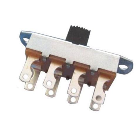
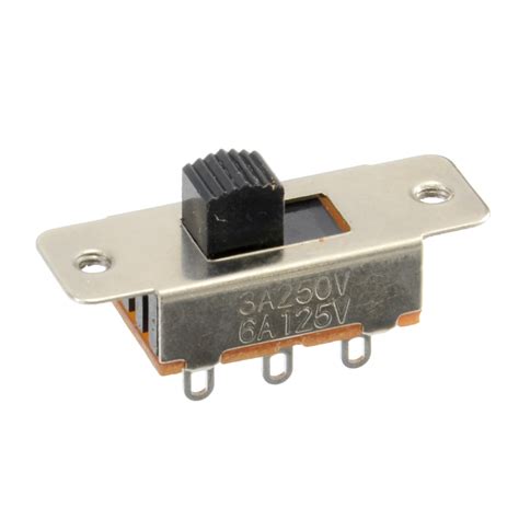
Slide Switches
If these look familiar, these are the two types of slide switch commonly used in "Offset" guitars - ie Jaguars, Mustangs, Jazzmasters, Jag-Stangs, Duo-Sonics. The top one is a standard Mustang/Jag-Stang/Duo-Sonic 3-way slide switch, and the one on the bottom is a Double Pole, Double Throw slide switch found in Jaguars and Jazzmasters. They basically slide back and fourth on two metal contacts that contact 2 contacts per side of the switch known as "poles", and each position is known as a "throw". But more on that later. These are generally used for switching between features and toggling features on and off.
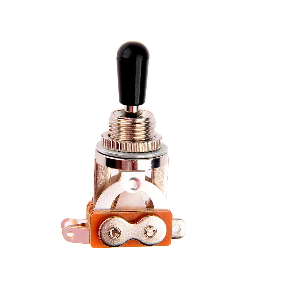
Leaf Toggle Switch
The Leaf-Style toggle is what you find in Gibson Style guitars (Les Pauls, SGs, Explorers, Flying Vees, B.C. Rich stuff, 2-humbucker no-pickguard stuff, etc). Basically they come in 3 types: the type seen here meant for Les Pauls that's a bit tall, the "low profile" version that's found in flatter instruments (SG, Explorer, Vee, Jazzmaster, etc.), and then a cheap version that's just a rectangular box with 3 contacts in the middle commonly found on import guitars. It's called a "leaf switch" because the contacts inside are little leafs that when the switch is tilted to one side or the other, it breaks contact with the opposing side, disabling whichever (usually pickup) device is connected to the lug that leaf corresponds to.
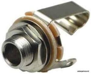
1/4" Phono Jack
All guitars use a 1/4" phono output jack. They come in 2 varieties, mono, which is the most commonly used, and stereo, which is also used as a switching jack for guitars with battery operated on-board electronics such as preamps or a sustainer system. They have contacts known as the tip, ring, and sleeve. The tip is the hot lead, the ring is the stereo connection for the right channel also used to link up a negative contact for the battery when the guitar is plugged in, and the sleeve is the rest of the body of the plug used as the ground.
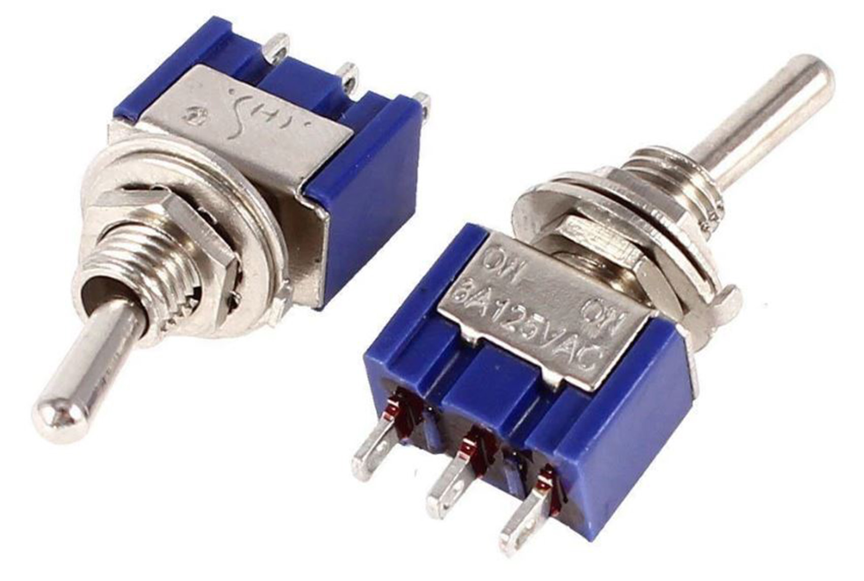
Mini-Toggle Switches
Probably the second most commonly seen switch(es) are these mini-toggle switches. These rose to popularity starting in the 1970's. The most popular applications for these switches are utility functions such as: coil splits, preamp enable/disable, phase reversal, series-parallel switching, built-in effects enable/disable, and various other utility functions, some more esoteric and weird than others.
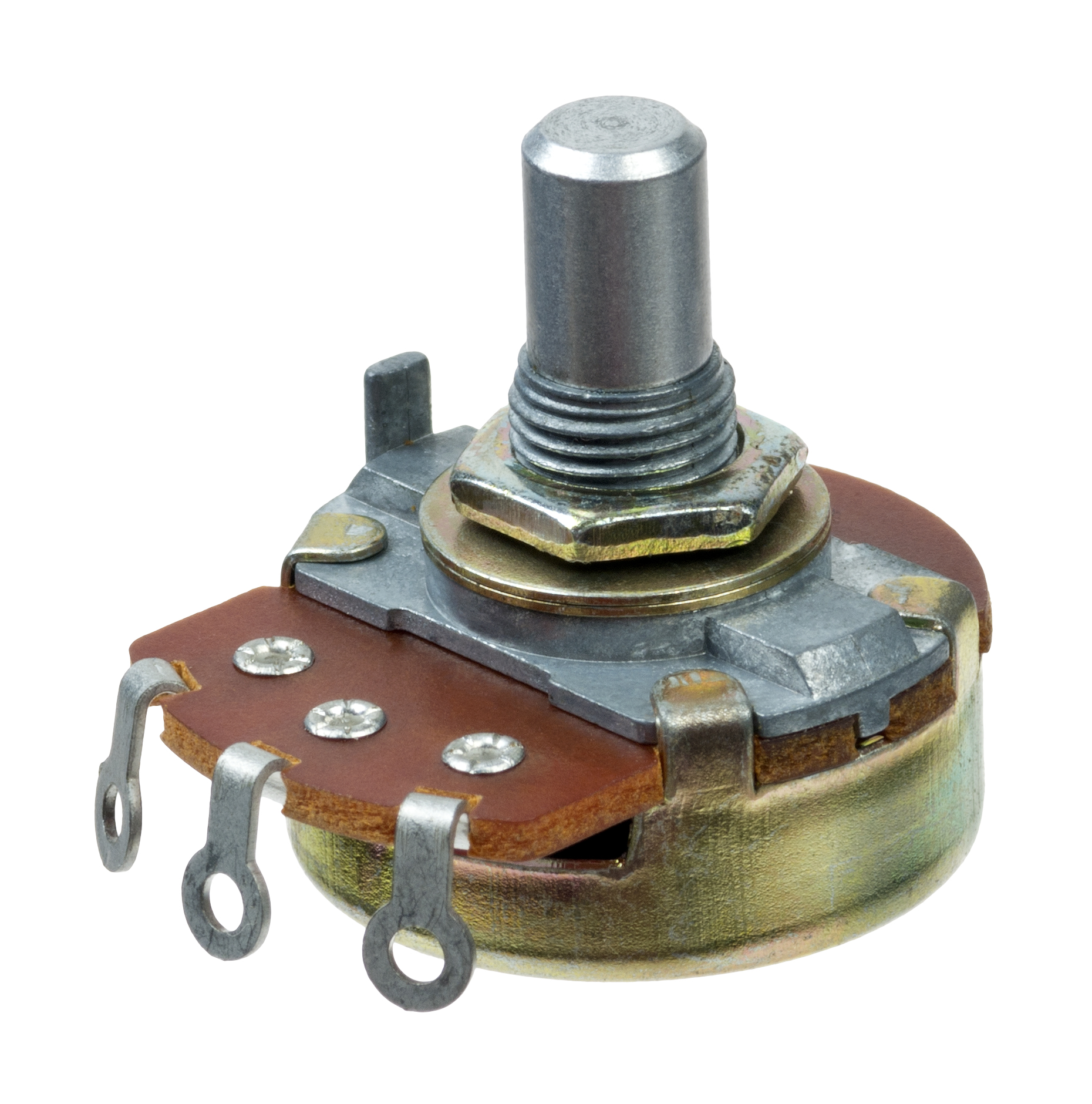
Potentiometer (aka "Pot")
A potentiometer is a "variable resistor", basically, a horeshoe shaped "track" is covered in carbon-based resistive material, and then a "wiper" contact in the middle sweeps across that contact, changing the resistor value between the maximum value of the pot, and 0 ohms resistance. The value scope, in a guitar-based application such as this, ranges from 250K ohms, used in single coil Stratocaster/Telecaster/Fender-STudent style instruments with single-coil pickups, all the way to 1MEG ohm for things like your Fender Jaguars and Jazzmasters. The two most common values are 250K and 500K though. Lower values of 25K and 50K are used for active pickups and special functions in Jaguars and Jazzmasters (ie Rhythm Circuit). These pots on the norm are "Audio Taper" or "Logarithmic" which means the human ear percieves it to be a linear change, vs. a "Linear" pot - which sounds almost like the volume/tone drops off instantly at a certain point.
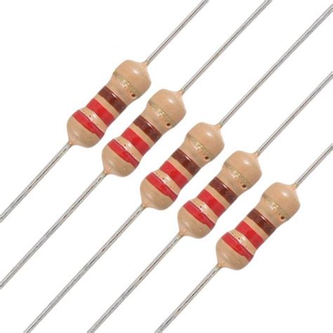
Resistor
The resistor is the basic version of the above, it adds "resistance" to electric current, and "burns off" the excess energy as "heat". Now, in guitar circuits, this heat is not feelable, but if we say, see these in your average 120 volt power supply - such as those found in a computer, you'll definatley feel heat coming off of them as they burn off the excess current in the form of heat. Resistors are measured in ohms (Ω) and can range all the way from a 0-ohm resistor - all the way to mega-ohms. Basically, most electronic stuff uses a metric system for measurement (ie pico, kilo, micro, etc...). Resistors are not used as often in the circuits inside the guitar, but they are sometimes, mostly on things like more advanced treble-bypass capacitor setups on the volume pot.
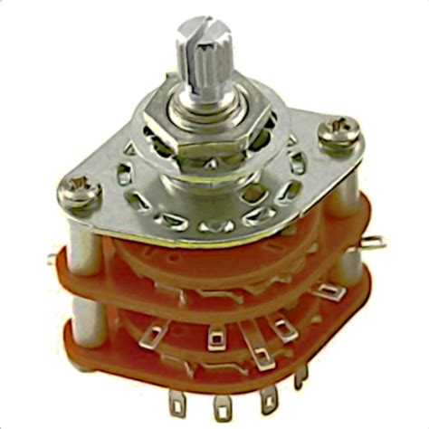
Rotary Switches
Rotary Switches of course are less commonly seen. The most commonly seen application on guitars are Paul Reed Smith guitars (Custom 22 and custom 24), usually as a cosmetic thing to make all three knobs look consistant. Rotary Switches are typically listed by pole, throw, and wafers. Ie, a 3 wafer, 8 way rotary switch can cover all of the selections on a 3-pickup single coil guitar, while a 2 wafer, 5-way, 3 pole switch can do some interesting things with 2 humbuckers.
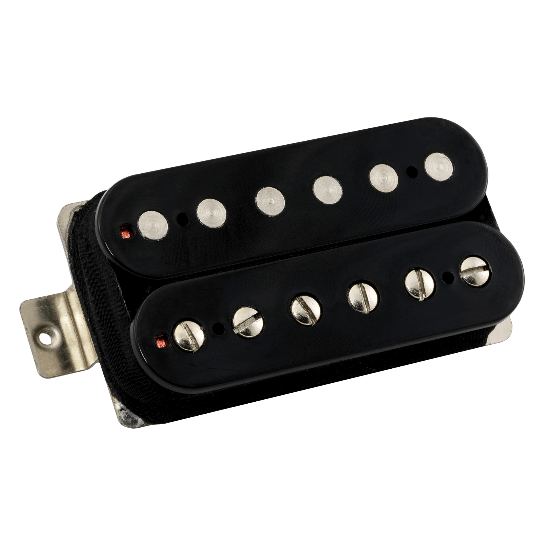
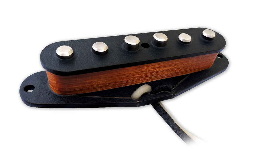
And obviously, we can't forget the pickups. These are what makes the sound you hear amplified by the amp. I have a whole section on these if you click the name of this item because there's a LOT to go over on the sound of a guitar pickup outside the scope of this page. There's tons of different pickups, but for this page, the most important distinction is if it's a double coil humbucker, or a single coil - for the most part (there are some oddballs like the "MOtherbucker" which has 3 coils, or these new "Quad Rails" thingies that are basically 2 double-coil hot rail style pickups on a standard humbucker frame).
Guitars can have as few as one pickup, or as many as four (that guy from the Dixie Dregs and some 1960's Teisco instruments), and the position of the pickups is what determines some of the sound as well. Most guitars will have one to three pickups installed. with the three most common schemes being the single-pickup superstrat or "Eddie Van-Halen" style wiring, the 2 pickup Telecaster style wiring, and the three pickup Strat type wiring.
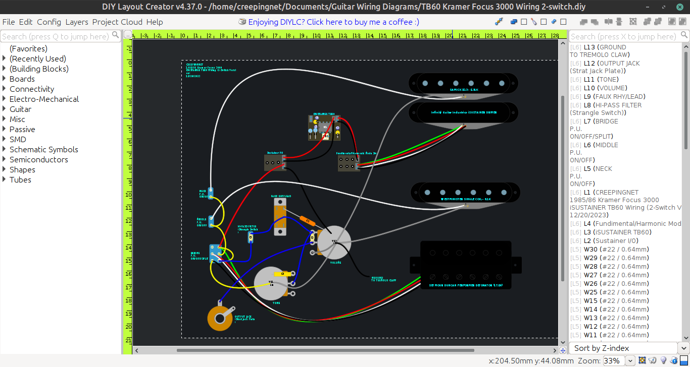
What Software do You Use for Your Diagrams?
I use DIY Layout Creator for all the current diagrams on this site. Previously I used Microsoft Paintbrush, and periodically also used Graf-X II as well. The latter two allowed me to make much clearer diagrams, expecially for my more complex circuits, but also required me to draw my own parts "libraries" of sorts to draw my diagrams with. DIY Layout Creator has some features that those did not have for development and possibly doing some quasi-business stuff (which I may end up doing).
So please excuse me a little on wiring diagrams on here being a little "messy" - it's just the nature of the program, but it's also a much more accurate representation of what you'll find inside of the typical solidbody electric guitar anyway. You're not going ot find straight lines and neatly tucked away wires, you're more likely to find wobbly lines everywhere and even a snakes nest of wires that will seem to make zero sense to you.
What this Page Is, and What It is Not
I probably should have put this first, but what this page is, is a very basic, sort of "for dummies" type tutorial to guitar wiring. It is not going to delve into math/algebra/calculus, it's not going to go on a EE Degree level explaination right on down to atoms, neutrons, and protons, and other stuff. I wrote this assuming most of my readers are either teenagers, or frazzle haired older rocker guys like myself who just want to modify, fix, or build their own Electric Guitars - that's it. I don't want to mislead anybody into thinking I'm some kind of Neal Degrasse Tyson of the guitar world, I'm not. So don't go filling up my in-box with nastygrams about how I "missed the point" or "am scientifically incorrect" - this is the basic b**** understanding that comes BEFORE you start learning the science behind it. IF you want science, go buy an engineering book. We're working on electric guitars here, not a NASA Space probe that has to last 40 years and fly all over outer space unattended.
BASIC GUITAR CIRCUITS
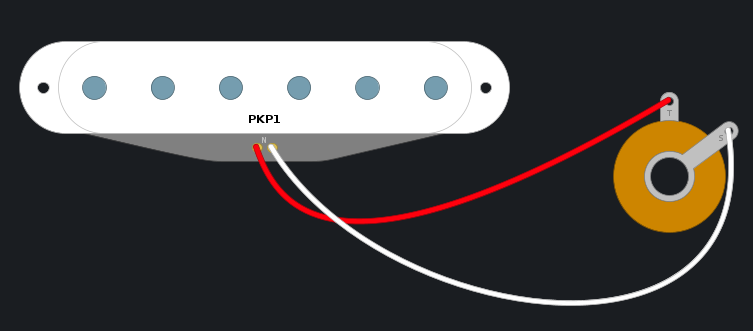
So here it is, the most basic guitar wiring diagram that's functional. I'm being dead serious here, so don't laugh too hard. What we have is your basic 6.4K Stratocaster pickup, wired into a simple 1/4" Phono output jack - that's it, that's ALL you need to get a pack of strings to sound awesome. And guess what - this is not that far from what many famous people have used....see below.
Okay, I'm sure Kurt Cobain's screaming countenance was enough to to get you excited here, it's not even a paragraph in and we're already talking about some famous guy's guitar's wiring. What? You thought the famous Martin D-18E was using those robot looking Dearmond pickups and original wiring, lol, think again. When Kurt played Unplugged, his Martin D-18E was rewired with a Bartolini 3AV acoustic pickup, bypassing the original wiring, which was wired direct to the output jack, and run into a Fender Twin Reverb amplifier disguised as a monitor wedge XD. I'm serious, as funny as that sounds, honestly, some of the coolest stuff has come from a simple wiring schematic.
All a pickup is, is basically the same thing as an electromagnetic generator, except instead of spinning a bunch of magnets near some coils - we are disturbing the magnetic field using strings to generate electricity in a coil and magnet assembly. String vibrates, generates electrical noises, those noises come out of the positive lead, and head towards the amplifier where they are made into loud noises. That's it.
However, this wiring diagram has some distinct disadvantages. For starters, you rely on the amp for all control of electronical sound elements - ie volume, tone, distortion, the guitar has little to no say in these things outside the player's hands. And while there is a lot you can do with just your hands and something wired up like this, there's also a lot you can't do. Like turn the guitar off in between songs, muffle the tone so it's less sharp on the fly, and if we wired in 2 pickups, you could not change between them.
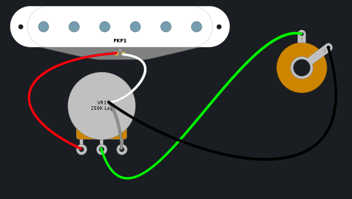
So now do you see how we've added that round can thing - a potentiometer (as viewed from the bottom), this is a Volume pot. How it works is, when it's at "10", the wiper contact in the middle is closest to the input lug (the far left in the picture) on the pot. This makes the "path of least resistance" - the path electricity always takes - to go to the output jack, giving us full volume from the pickup. When it's at 0, the wiper is closest to the ground and there's 250,000 ohms of electronic resistance between the pickup hot lead and the output, so all the energy going to ground, is comign from the ground side, thusly, no sound at all. Literally, if we wired in a 2 conductor humbucker pickup into this, and changed the potentiometer to a 500K, we would literally have Edward Van-Halen's usual guitar circuit from the late 70's early 80's.
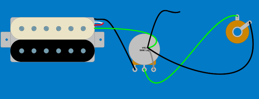
So above, here we have basically what was the wiring on the original Frankenstrat. If the wire colors look weird on the humbucker, let's just say I'm using Seymour Duncan's wiring codes for most of these pickups. Basically, Ed's humbucker would have been a 2 conductor pickup - which means it only had a hot and ground, just like a single coil, the hot would feed into the leftmost leg of the pot, the ground would go to the pot casing. That extra wiring hanging from the top - is the ground wire that connects to the bridge, and basically, makes the strings a part of the defense against noise and interference, and the human body also seems to help with that quite a bit as well. If you've ever looked in the back of a guitar with a strat or Floyd Rose type whammy bridge, and wondered what that wire soldered to the "claw" in back is - well, that's that wire.
This type of wiring was reproduced into a LOT of 1980's "metal" guitars and "superstrats" (Charvel San Dimas, Jackson Dinky, Kramer Pacer Special, Kramer Baretta, Washburn Force-series, some simple Ibanez designs), and was literally an outgrowth of Eddie's lack of knowledge on guitar electronics at the time, but turned out to have some serious tonal benefits. Basically, more pure tone, and more sustain due to less magnetic pull from more than one pickup, and less interference from potential bleed from other pickups or out-of-spec components.
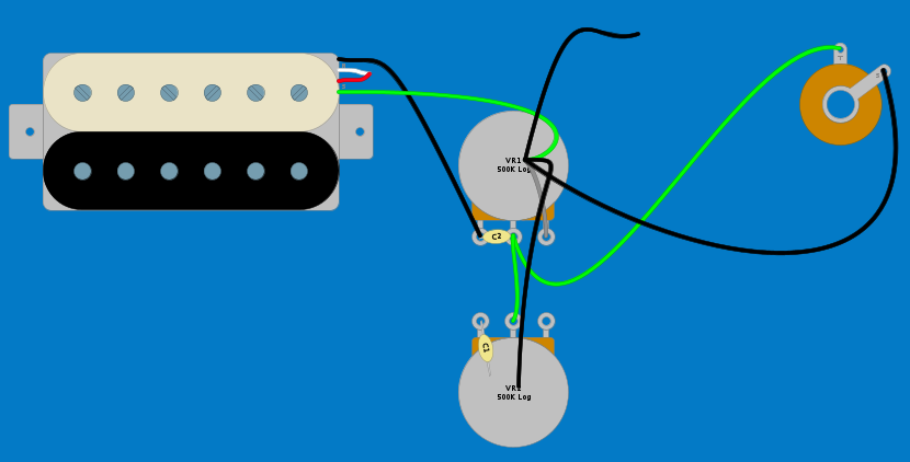
Now let's add a tone control to this picture....
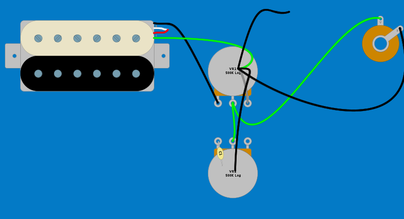
So now we go from Eddie, to Fender here. If we swapped out the 500K pots here with 250K, and the humbucker with a single coil, this would basically be the Fender Musicmaster/Bronco circuit. 1 Volume, 1 Tone, and a single pickup. Notice the addition of another potentiometer into the mix, and then a little tan "blurb" on the left side lug? That "blurb" is a capacitor, and it's grounded off to the pot casing.
Capacitors are used in guitar circuits as a form of "filter" for frequencies. What we have here is called a "Low Pass Filter" - that's all a tone control is, it sends the higher frequencies off to ground, giving the guitar that muffled "warm" kind of sound, associated with Jazz music. An easy way to remember these ideas, is if you run the current off to ground through a cap, it cuts high frequencies, if you run the current THROUGH a capacitor to a hot-lead on the other side, it cuts LOW frequencies - ie a high pass filter. Let's add another capacitor and see one more variation on this circuit as we expand it.
Now look closely - notice anything different? That little tan blurb on the volume pot between lugs 1 & 2 (from left to right?) - this is a capacitor as well, that let's the high frequencies pass. What this is called, is a "Treble Bypass" capacitor. This is the most basic kind, and it's typically a capacitor between 220pf and 1500pf (pico farads). My personal favorite is the 470pf (code 471) on my own instruments.
This kind of wiring was actually pretty popular in the 80's as well, including some budget guitars such as the Memphis A2-TR, Gremlin, Jaguar (not the Fender, the brand Jaguar), and many other single pickup, entry level, superstrat-derived guitars.
So now, let's start introducing multiple pickups into the mix. Let's start talking 2 pickup circuits.
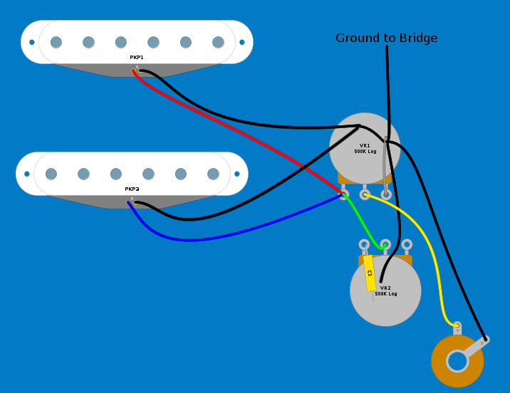
2 Pickup Circuits
Let's start by taking a look at a non-switchable 2-pickup circuit - the Harmony H803/H804!

 I use DIY Layout Creator for all the current diagrams on this site. Previously I used Microsoft Paintbrush, and periodically also used Graf-X II as well. The latter two allowed me to make much clearer diagrams, expecially for my more complex circuits, but also required me to draw my own parts "libraries" of sorts to draw my diagrams with. DIY Layout Creator has some features that those did not have for development and possibly doing some quasi-business stuff (which I may end up doing).